Wireless electronic apparatus and controlling method thereof

A wireless electronic and wireless signal technology, applied in the directions of radio transmission systems, antenna supports/installation devices, antennas, etc., can solve the problems of increased signal power and infeasibility

Inactive Publication Date: 2007-01-31
ACER INC
View PDF0 Cites 3 Cited by
  • Summary
  • Abstract
  • Description
  • Claims
  • Application Information

AI Technical Summary

Problems solved by technology

When the gain of the antenna increases, although its ability to receive signals increases, the power of the transmitted signal will also increase at the sam

Method used


Image

  • Wireless electronic apparatus and controlling method thereof
  • Wireless electronic apparatus and controlling method thereof
  • Wireless electronic apparatus and controlling method thereof

Examples


Embodiment Construction

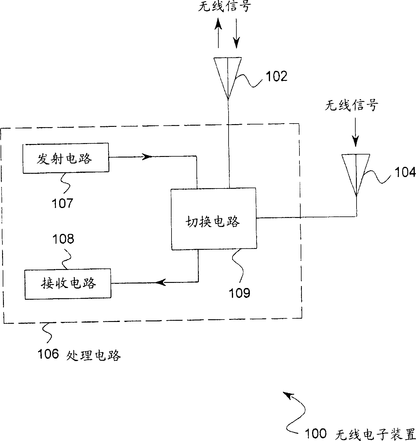
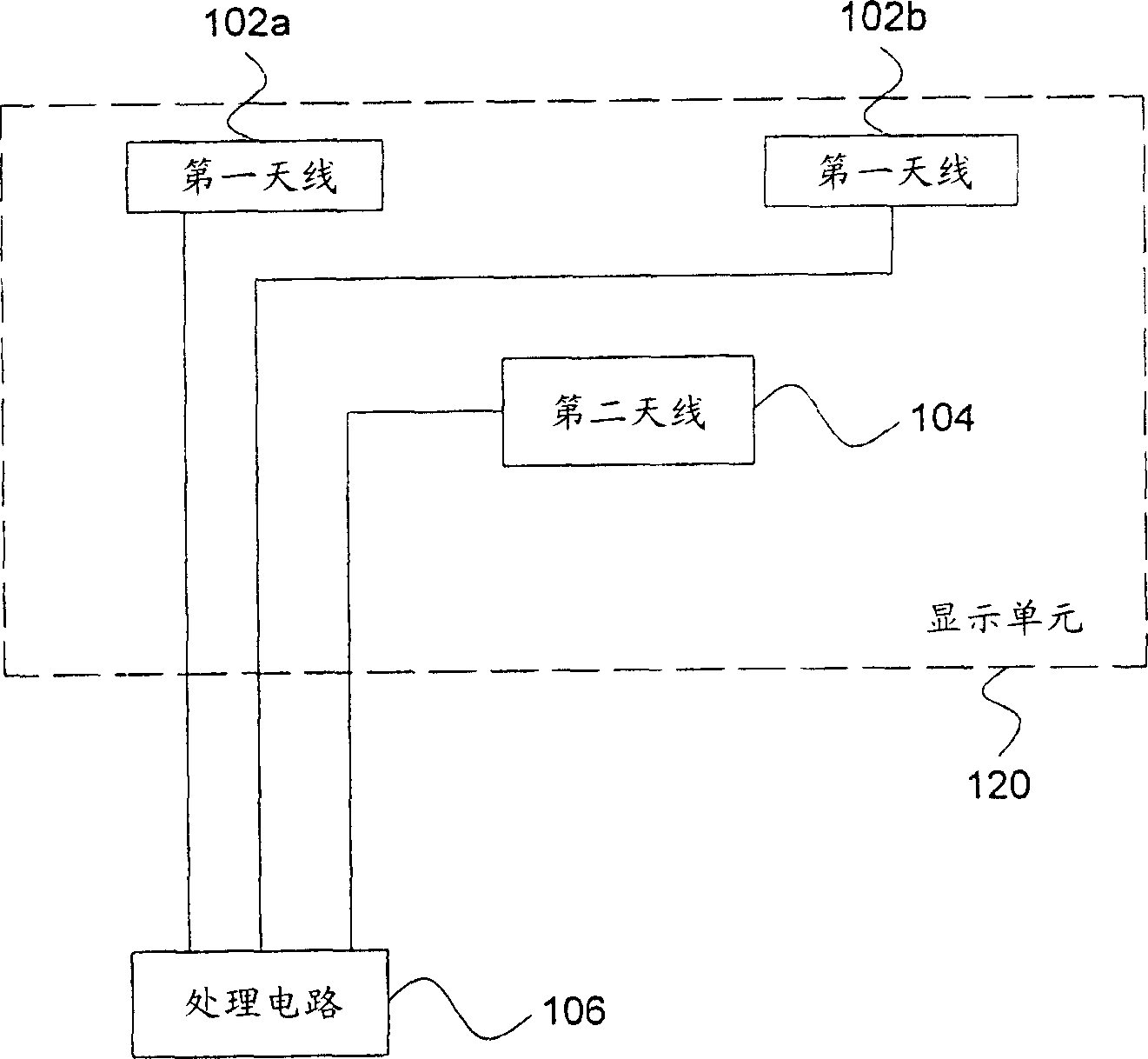
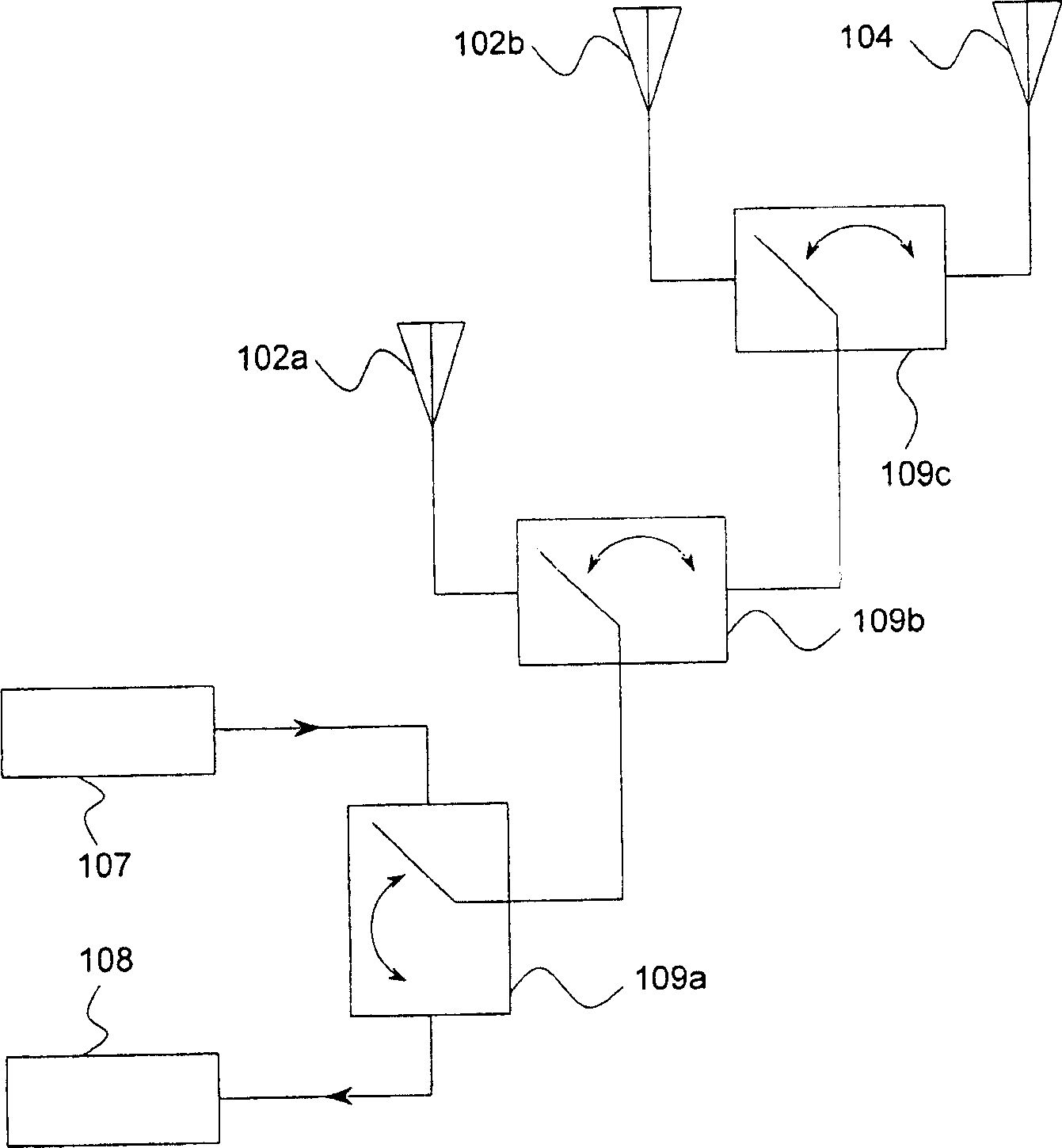
[0027] The present invention relates to a wireless electronic device, such as a personal computer, a notebook computer, a personal digital assistant, a mobile phone, a mobile audio-visual device with wireless function, or any electronic device that uses an antenna for wireless communication. The antenna in the present invention can be a slot antenna, an inverted F antenna, a notch antenna or other known antenna structures, and is not limited to an omni-directional antenna or a directional antenna ( directional antenna), built-in antenna or external antenna. In addition, the antenna of the present invention may be a single-band, dual-band, or triple-band antenna. In one embodiment, the antenna of the present invention can be designed and applied to ISM and U-NII wireless local area network (WLAN). In another embodiment, the antenna of the present invention is used for wireless communication under the IEEE 802.11a or 802.11g standard. In another embodiment, the antenna of the presen...


PUM


Abstract

The invention is a wireless electronic device, comprising a first antenna, a second antenna, and a processing circuit, where the first antenna has a first gain and the second antenna has a second gain, and the processing circuit selectively executes a first or second mode; as executing the first mode, the processing circuit transmits and receives wireless signals through the first antenna; and executing the second mode, transmits wireless signal through the first antenna and receives wireless signal through the second antenna.

Description

Technical field [0001] The invention relates to a wireless electronic device, an antenna module, and a control method of the wireless electronic device. Background technique [0002] With the development of wireless local area network (WLAN) technology, under the IEEE 802.11a or 802.11g standards, the data transmission rate of wireless signals can reach up to 30Mbps, which can be used to receive wireless signals of high-definition digital TV. . However, the data transmission rate is affected by the transmission distance. At present, users can only watch high-definition digital TV with wireless electronic devices within a limited distance from a wireless signal source (such as a wireless access point, AP). [0003] As mentioned above, in wireless communication, wireless signals will attenuate with the transmission distance, that is, the longer the transmission distance, the lower the data transfer rate that can be supported. If it is desired to increase the signal transmission dis...

Claims


Application Information

Patent Timeline
IPC IPC(8): H04B1/40H04B1/44
CPCH01Q3/24H01Q1/24H04B7/0805H04B7/0602
Inventor 林永森
Owner ACER INC
Why Eureka
Try Eureka