Needle thread passing device

A needle threading and threading technology, which is applied in the field of needle and thread threading devices, can solve the problems of large devices and inconvenient storage, and achieve the effects of excellent accommodation, good accommodation, and good space efficiency

Inactive Publication Date: 2010-06-23
KOTOBUKI & CO LTD +1
View PDF7 Cites 9 Cited by
  • Summary
  • Abstract
  • Description
  • Claims
  • Application Information

AI Technical Summary

Problems solved by technology

[0003] However, in the needle thread threading device of Patent Document 1, since a space for swinging the operating member is provided in the main body, the main body becomes larger, the device becomes larger, and there are problems such as inconvenient storage.

Method used


Image

  • Needle thread passing device
  • Needle thread passing device
  • Needle thread passing device

Examples


Embodiment Construction

[0040] Embodiments of the present invention will be described below using the drawings.

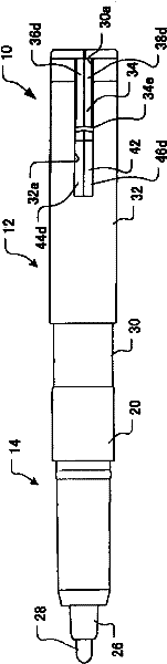
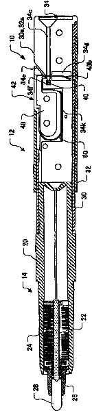
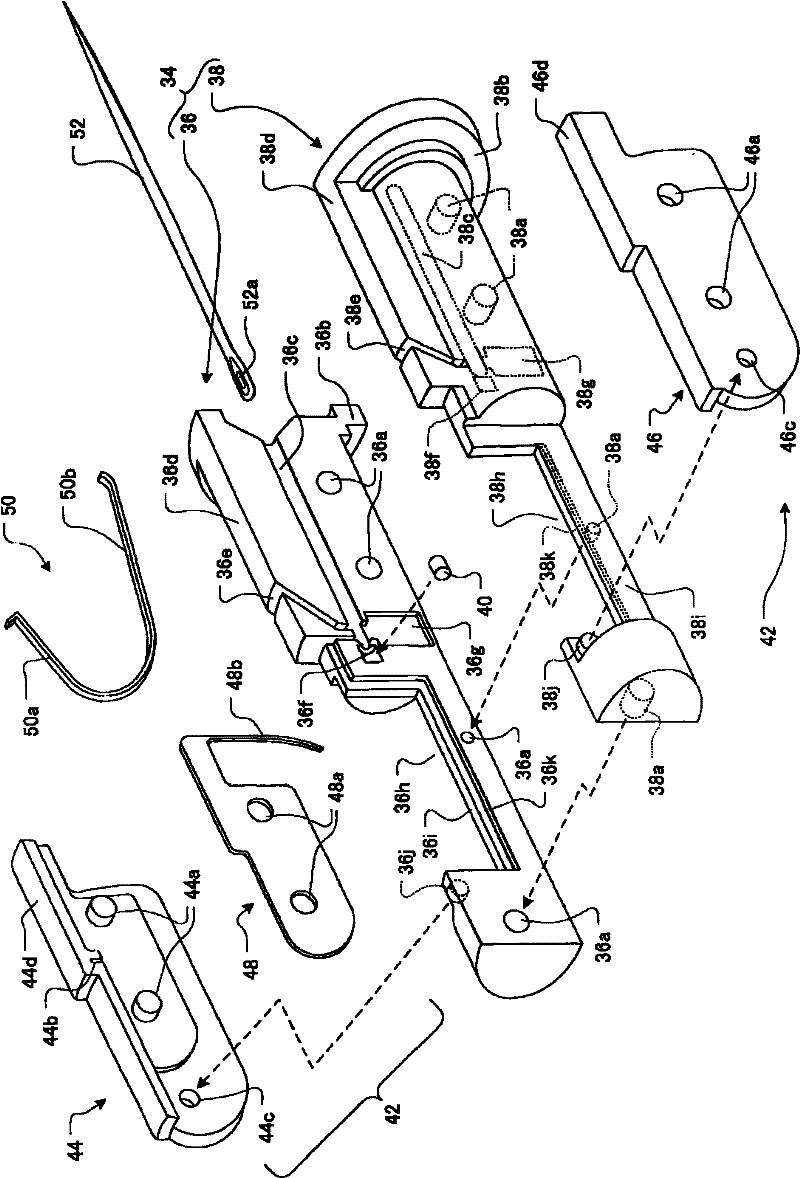
[0041] figure 1 It is an overall view when the needle thread threading device according to the first embodiment of the present invention is stored, figure 2 It is a longitudinal sectional view at the time of storage, image 3 It is an exploded perspective view of the inside of the threading device.

[0042] In the figure, the needle thread threading device 10 of this example is formed as a slender cylindrical structure as a whole, a needle thread threading unit 12 constituting the needle thread threading device 10 is provided at one end side, and a writing tool unit 14 is provided at the other end side. , the two units are connected axially to become one. As a method of integrating the two units, any joining method such as press-fitting, bonding, and screw fitting may be used, and the integration may be detachable or non-detachable. Of course, the pen unit itself may be omitted, and th...


PUM


Abstract

A needle thread passing device small-sized and conveniently stowable. A needle receiving member (34) has formed therein a needle inserting hole (34c) and a thread inserting slit (34e) having an angle relative to the needle inserting hole (34c). A thread passing member (42) is adapted to be movable between a position at which the thread passing member (42) is separated from the needle receiving member (34) and a position at which the thread passing member (42) is located proximate to the needle receiving member (34). Also, the thread passing member (42) has a thread passing pin (48b) which can, when the thread passing member (42) moves fromthe separated position to the proximate position, push out a thread, inserted in the thread inserting slit (34e), into a needle hole (52a) in a needle (52) inserted in the needle inserting hole (34c). A cover (32) is adapted to be movable relative to a body (30) in which the needle receiving member (34) is housed. The thread passing member (42) is constantly urged to the position at which the thread passing member (42) is separated from the needle receiving member (34). The cover (32) is adapted to be movable between a restraining position for restraining the thread passing member (42) at a position at which the thread passing member (42)is located proximate to the needle receiving member (34) and a permitting position for permitting the thread passing member to move between the separated position at which the thread passing member is separated from the needle receiving member and the proximate position at which thread passing member is located proximate to the needle receiving member.

Description

technical field [0001] The present invention relates to a needle thread threading device for simply threading a thread in a needle hole. Background technique [0002] Conventionally, as such a needle thread threading device, a device described in Patent Document 1 (Japanese Patent No. 3315364 ) is known. According to this device, a needle insertion cylinder having a bottomed needle insertion hole is erected on a main body having a base surface, and a needle connecting the inserted needle is formed at the lower part of the needle insertion cylinder in a direction intersecting the needle insertion hole. For the threading hole of the threading hole, a thread mounting part is provided near the entrance of the threading hole, and the thread locking piece provided on the working part is inserted through the working part provided in the main body by the pressing force of the pressing part provided on the main body. It can be freely set in the threading hole. When the pressing mem...

Claims


Application Information

Patent Timeline
Patent Type & Authority Applications(China)
IPC IPC(8): D05B87/02
CPCD05B87/02D05B85/00D05B87/00
Inventor 野口芳男齐藤受理
Owner KOTOBUKI & CO LTD
Why Eureka
Try Eureka