

Two-stage rolling rotor-type expander
A rolling rotor type and expander technology, which is applied in the direction of machines/engines, combined engines, rotary piston engines, etc., can solve problems such as the decrease of expander efficiency, reduce flow loss, reduce length and volume, and improve expansion efficiency Effect
- Summary
- Abstract
- Description
- Claims
- Application Information
AI Technical Summary
Problems solved by technology
Method used
Image

Examples
Embodiment Construction
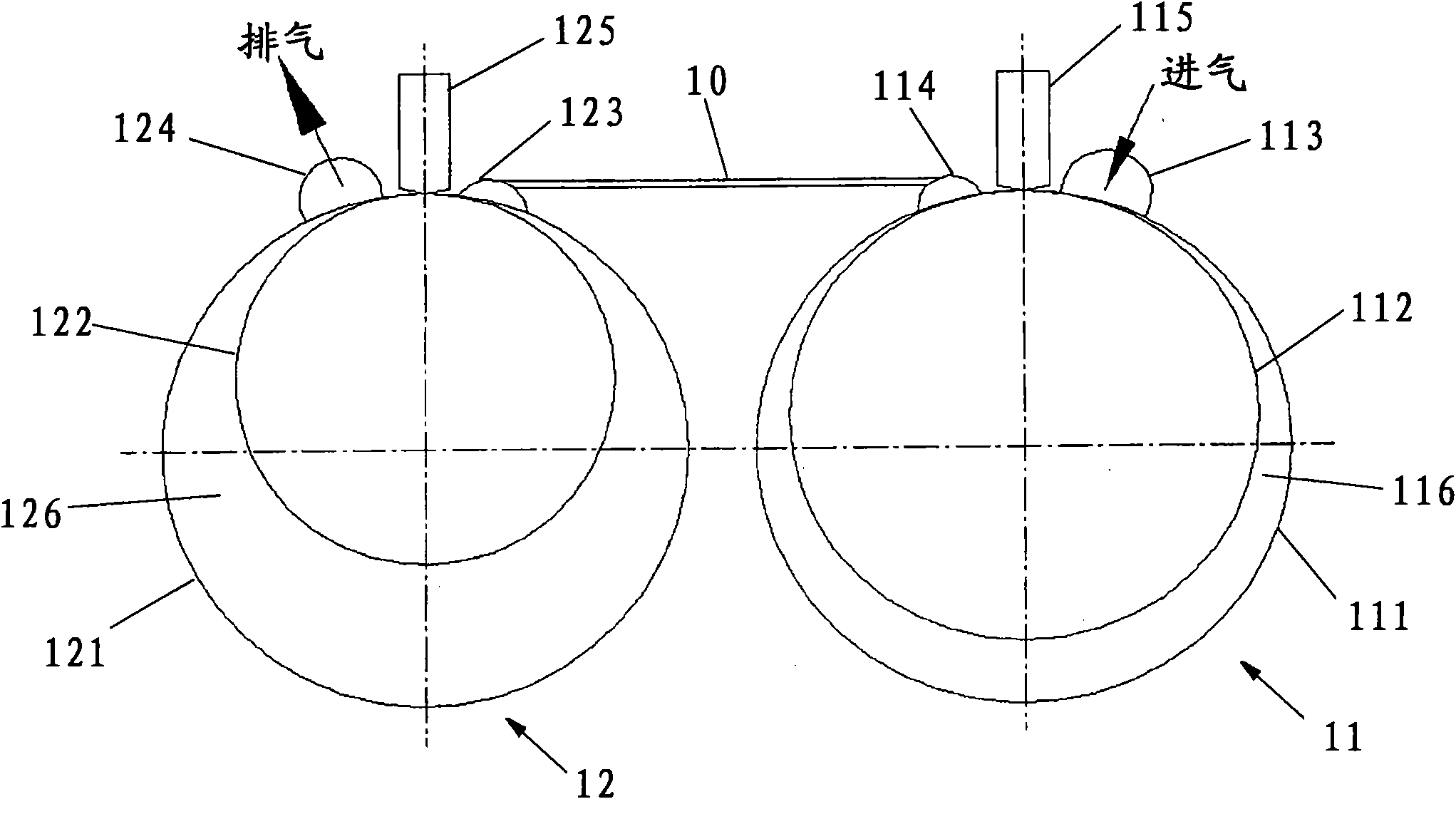
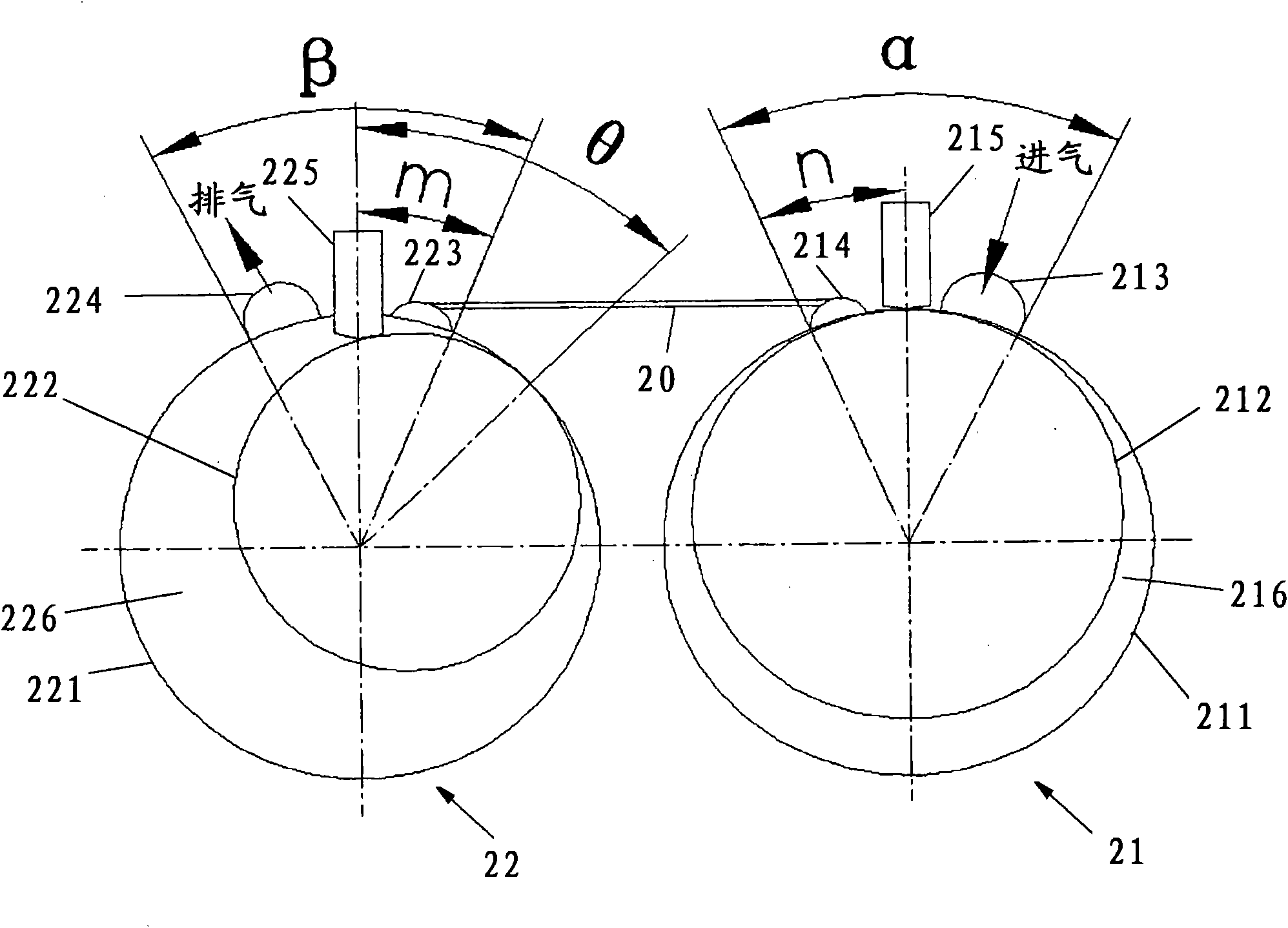
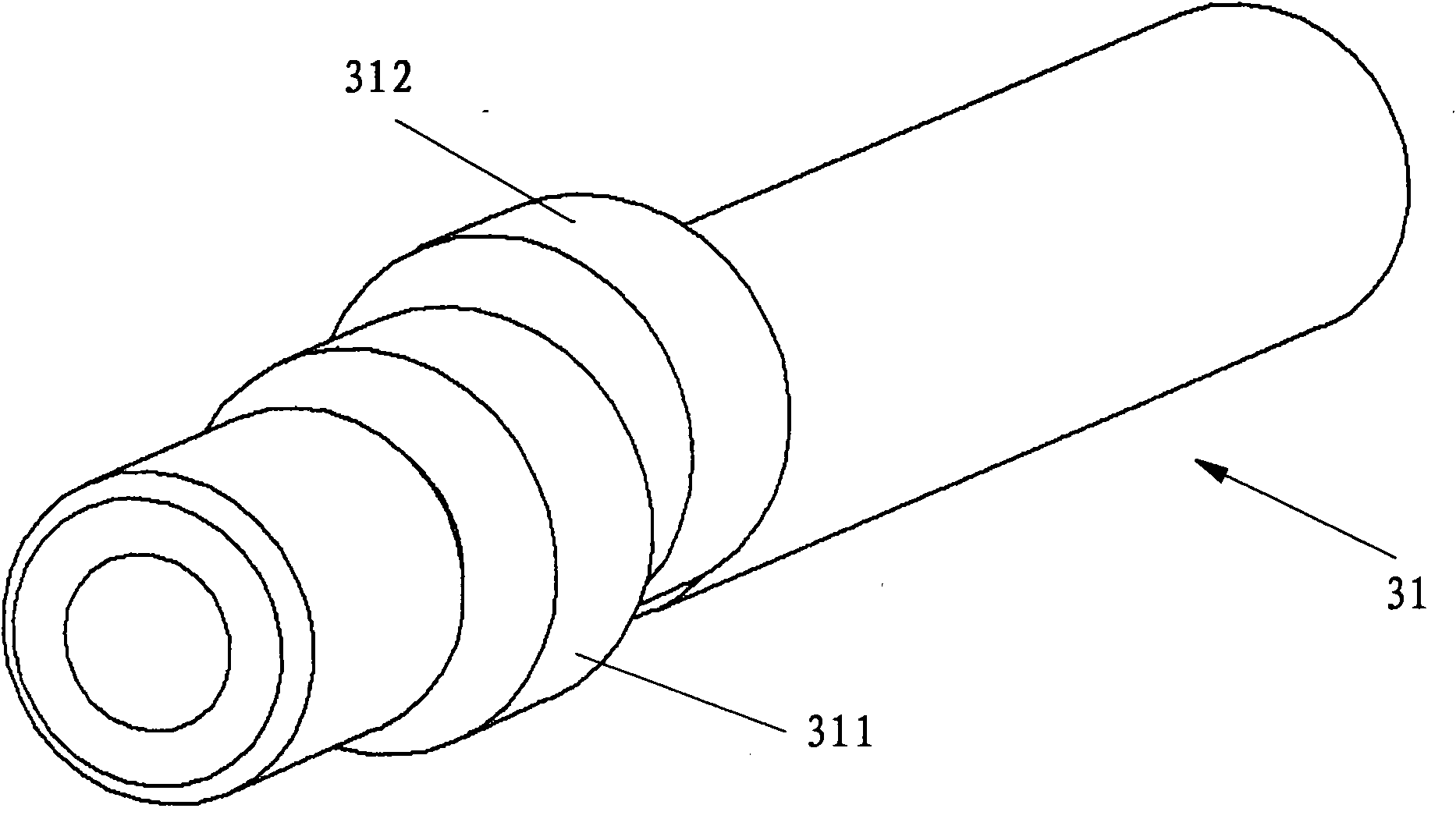
[0015] figure 2 shows a two-stage rolling rotor expander according to a first embodiment of the invention, image 3 The crankshaft in this two-stage rolling rotor expander is shown. The two-stage rolling rotor expander includes a first expansion unit 21 , a second expansion unit 22 , an intermediate plate between the first and second expansion units, and a crankshaft 31 shared by the first and second expansion units.
[0016] The first expansion unit 21 includes a first cylinder 211 with a first suction port 213 and a first exhaust port 214 , a first piston 212 , and an angle between the first suction port 213 and the first exhaust port 214 . The first blade 215 in. The first cylinder 211 and the first piston 212 define a first cavity 216 . The second expansion unit 22 includes a second cylinder 221 having a second suction port 223 and a second exhaust port 224 , a second piston 222 , and a The second blade 225 in. The second cylinder 221 and the second piston 222 define...
PUM
 Abstract
Description
Claims
Application Information