

Indirect lighting lamp cover device
A technology of lighting lamps and lighting covers, applied in lighting devices, non-electric lighting devices, portable lighting devices, etc., can solve problems such as poor working efficiency, difficulties, and milky white plastic boards hindering work, and achieve good appearance and ensure working space Effect
- Summary
- Abstract
- Description
- Claims
- Application Information
AI Technical Summary
Problems solved by technology
Method used
Image

Examples
Embodiment approach 1
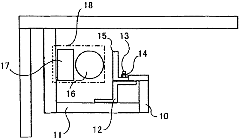
[0061] pass figure 1 The indirect lighting lamp cover according to Embodiment 1 of the present invention will be described.
[0062] figure 1 It is a front view showing the structure of the first embodiment of the indirect lighting lamp cover of the present invention. On the bottom surface 11 of the indirect lighting lamp cover 10, a fixing bracket 12 made of a Z-shaped milky white plastic plate is fixedly installed. In addition, A stud 13 is attached to the upper surface of the fixing bracket 12 , and a nut 14 is inserted into the stud 13 in a detachable manner.
[0063] In addition, on the upper part of the fixing bracket 12, an L-shaped milky white plastic plate 15 is fixedly installed by passing a stud 13 through a hole (not shown) provided on the lower surface thereof and tightening it with a nut 14 .
[0064] In this case, the milky white plastic plate 15 is enough to make the lighting fixture 18 made of the lighting source 16 and the reflector 17 etc. visible from t...
Embodiment approach 2
[0067] pass figure 2 An indirect lighting lamp cover according to Embodiment 2 of the present invention will be described.
[0068] Additionally, the following in Figure 2 to Figure 9 Among them, lighting fixtures and indirect lighting covers, etc. figure 1 Since they have the same structure, the same reference numerals are assigned to the structural parts, and the detailed description of the parts will be omitted.
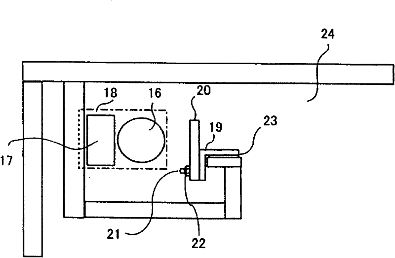
[0069] figure 2 It is a front view showing a second embodiment of the indirect lighting lamp cover of the present invention, and a milky white plastic plate 20 is attached to the side of an L-shaped fixing bracket 19 made of, for example, a steel plate.
[0070] This installation is that the stud 21 that is located at the side lower part of fixed bracket 19 penetrates in the hole (not shown) that is offered in the lower end of milky white plastic plate 20 and tightens with nut 22 and is fixedly installed.
[0071] And, on the lower part of the other surfac...
Embodiment approach 3
[0075] use image 3 An indirect lighting lamp cover according to Embodiment 3 of the present invention will be described.
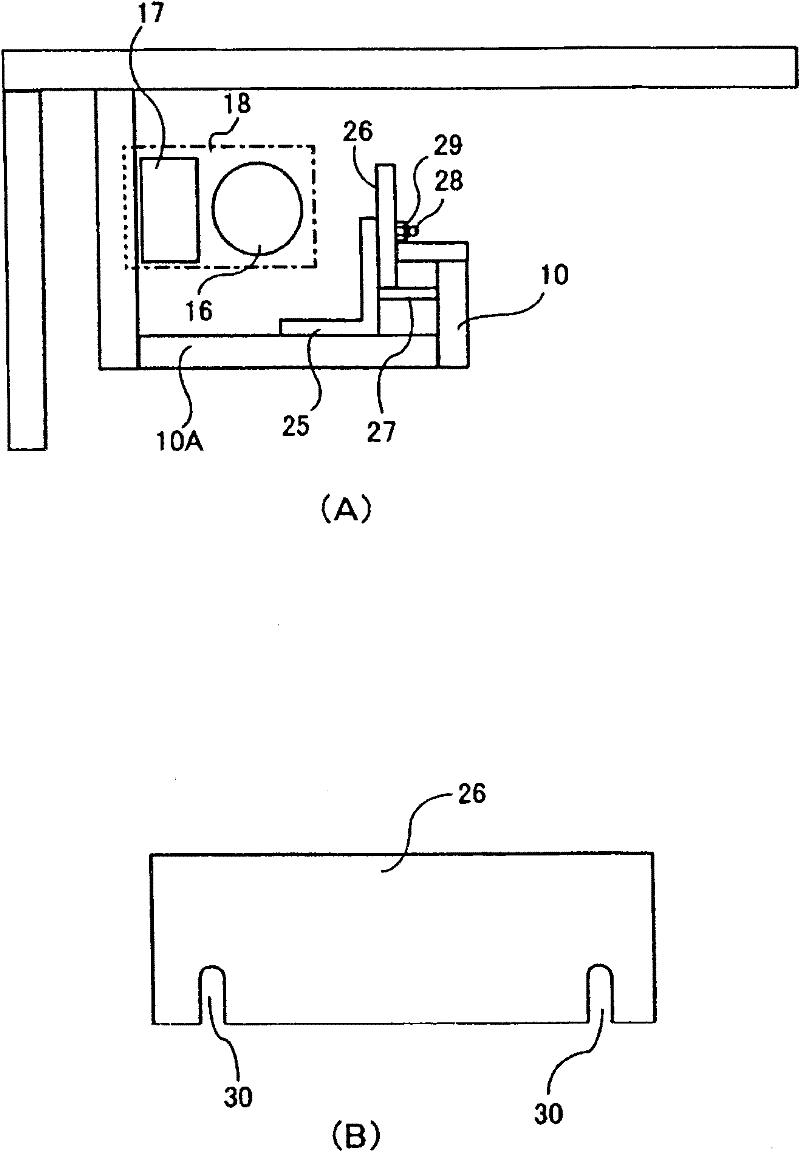
[0076] image 3 It is a block diagram showing the third embodiment of the indirect lighting lamp cover of the present invention, image 3 (A) is a front view of an indirect lighting fixture cover, image 3 (B) is the front view of the milky white plastic plate.
[0077] exist image 3 In (A), the L-shaped fixed bracket 25 made of steel can be freely inserted into the gap of the size of the milky white plastic plate 26 from the gap between the back surface and the upper part of the indirect lighting cover 10. On the bottom surface 10A of the indirect lighting cover 10 .
[0078] In addition, a mounting table 27 on which the milky white plastic plate 26 is placed is attached to the middle portion of the fixed bracket 25, and the lower portion of the milky white plastic plate 26 inserted into the above-mentioned gap is placed.
[0079] And then, on the...
PUM
 Abstract
Description
Claims
Application Information