Supercharge Your Innovation With Domain-Expert AI Agents!

Sealed dual plunger switch assembly with simultaneity

A double plunger, plunger technology, applied in the direction of electric switches, electrical components, emergency actuators, etc., can solve the problems of expensive installation bracket system, complex and so on

Inactive Publication Date: 2010-07-07
HONEYWELL INT INC
View PDF4 Cites 0 Cited by
  • Summary
  • Abstract
  • Description
  • Claims
  • Application Information

AI Technical Summary

Problems solved by technology

In many cases, achieving these relationships will be complicated by the fact that normal manufacturing tolerances alone may be greater than the total travel of the switch (return plunger travel plus travel difference plus maximum allowable overtravel) requiring the use of expensive and complex mounting bracket system

Method used


Image

  • Sealed dual plunger switch assembly with simultaneity
  • Sealed dual plunger switch assembly with simultaneity
  • Sealed dual plunger switch assembly with simultaneity

Examples


Embodiment Construction

[0022] The specific values ​​and structures described in these non-limiting examples may vary and are cited herein merely to illustrate at least one embodiment of the invention and not to limit the scope thereof.

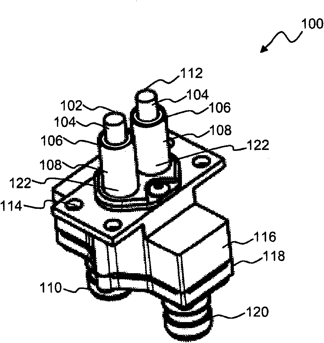
[0023] refer to figure 1 , illustrates a perspective view of a dual plunger switch assembly 100 according to a preferred embodiment. pay attention to Figure 1-Figure 7 In , the same or similar parts or elements are generally identified with the same reference numerals. The dual plunger switch assembly 100 includes a housing 116 surrounding the switch subassembly 102 and the switch subassembly 112 . Switch assembly 100 further includes a pair of electrical connectors 110 and 120 extending through cover plate 118 attached to housing 116 to communicate with external circuitry.

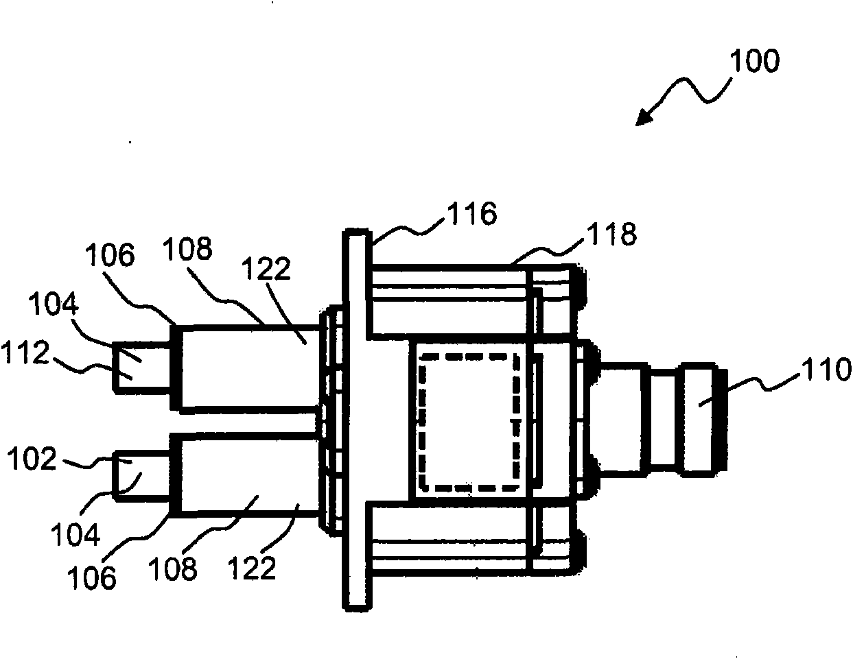
[0024] refer to figure 2 , illustrating according to the preferred embodiment in figure 1 A side perspective view of the dual plunger switch assembly 100 shown in ;

[0025] refer to ...


PUM


Abstract

A sealed dual plunger switch assembly includes two switch sub-assemblies comprising plunger actuating mechanisms and basic switches. The sub-assemblies can be inserted into an overall enclosure using shims in order to position their operate points in the desired range relative to the enclosure's mounting surface. The enclosure is then sealed using a combination of covers, gaskets, O-rings, connectors and potting. The sub-assemblies individually and / or simultaneously receive actuation inputs within a fixed distance from the assembly's mounting surface.

Description

technical field [0001] Embodiments generally relate to electrical switches. Embodiments also relate to plunger actuation mechanisms for use in switchgear. Embodiments also relate to sealed switch subassemblies within a common housing for maintaining actuation inputs at different plunger positions, operating simultaneously within a fixed distance from a mounting surface of the assembly. Background technique [0002] Many types of switching mechanisms are used in residential, commercial, industrial and military applications. A particular application of this type of switch mechanism involves a push button switch comprising a plunger movable along an axis relative to a base and which actuates a switch member when the plunger is depressed. Typically, the plunger is connected to a button depressible by a human finger. Some switch mechanisms actuate the switch each time the button and plunger are depressed, while others, known as alternating-action devices, actuate on one press ...

Claims


Application Information

Patent Timeline
Patent Type & Authority Applications(China)
IPC IPC(8): H01H13/00
CPCH01H13/70H01H13/14H01H13/06H01H2221/072H01H13/186
Inventor M·J·斯卡卢普卡M·J·布罗斯
Owner HONEYWELL INT INC
Features
  • R&D
  • Intellectual Property
  • Life Sciences
  • Materials
  • Tech Scout
  • Unparalleled Data Quality
  • Higher Quality Content
  • 60% Fewer Hallucinations
Learn More