
Fluorescent lamp dimming control circuit and dimmable fluorescent lamp thereof

A dimming control circuit and fluorescent lamp technology, which is applied in the field of fluorescent lamps, can solve problems such as unsatisfactory dimming effects, and achieve soft dimming effects, accurate control of output illuminance, and continuous dimming effects

Inactive Publication Date: 2012-12-05
OCEANS KING LIGHTING SCI&TECH CO LTD +1
View PDF0 Cites 0 Cited by
  • Summary
  • Abstract
  • Description
  • Claims
  • Application Information

AI Technical Summary

Problems solved by technology

[0004] The technical problem to be solved by the present invention is to provide a fluorescent lamp dimming control circuit using voltage and current closed-loop control and a dimmable fluorescent lamp using the circuit in view of the above-mentioned unsatisfactory dimming effect of the prior art.

Method used


Image

  • Fluorescent lamp dimming control circuit and dimmable fluorescent lamp thereof
  • Fluorescent lamp dimming control circuit and dimmable fluorescent lamp thereof
  • Fluorescent lamp dimming control circuit and dimmable fluorescent lamp thereof

Examples


Embodiment Construction

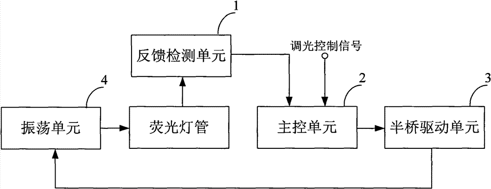
[0023] Such as figure 2 Shown is a structural block diagram of an embodiment of the fluorescent lamp dimming control circuit of the present invention. The fluorescent lamp dimming control circuit of the present invention includes a feedback detection unit 1 , a main control unit 2 , a half-bridge drive unit 3 and an oscillation unit 4 .

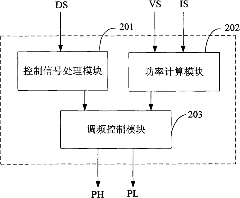
[0024] Wherein, the feedback detection unit 1 includes a current detection unit that detects the operating current of the fluorescent tube to obtain a sampling current, and a voltage detection unit that detects the operating voltage of the fluorescent tube to obtain a sampling voltage; the main control unit 2 is used to generate The first pulse and the second pulse are the same but in opposite directions, and the frequency of the first pulse and the second pulse is controlled and adjusted according to the sampling current, the sampling voltage and the dimming control signal input from the outside; the half-bridge drive unit 3 is based on the...


PUM


Abstract

The invention relates to a fluorescent lamp dimming control circuit and a dimmable fluorescent lamp using the circuit. The control circuit comprises a feedback detection unit (1), a main control unit (2), a half-bridge drive unit (3) and an oscillation unit (4), wherein the feedback detection unit (1) comprises a current detection unit (101) which detects the working current of a fluorescent lamptube to obtain a sampling current and a voltage detection unit (102) which detects the working voltage of the fluorescent lamp tube to obtain a sampling voltage; and the main control unit (2) is usedto produce a first pulse and a second pulse with the same frequency, the same amplitude and opposite directions and controls and regulates the frequency of the first pulse and the second pulse according to the sampling current, the sampling voltage and externally input dimming control signals. The invention uses a voltage and current loop control circuit to realize dimming control, can accuratelycontrol the output power of the fluorescent lamp tube, and accurately controls output illumination, and the dimming is more continuous and stable.

Description

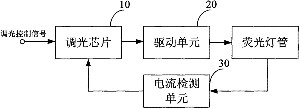
technical field [0001] The present invention relates to the technical field of fluorescent lamps, more specifically, to a dimming control circuit for fluorescent lamps and a dimmable fluorescent lamp using the circuit. Background technique [0002] With the development of science and technology, fluorescent lamps play a vital role in people's lives. Such as figure 1 Shown is a structural block diagram of a traditional fluorescent lamp dimming control circuit. The control circuit adopts current loop control, including a dimming chip 10, a drive unit 20 and a current detection unit 30. The dimming chip 10 judges the working power of the fluorescent tube according to the current collected by the current detection unit 30, and then controls the dimming with the external input. Signals are compared to achieve dimming control. [0003] Dimming of a fluorescent lamp is to change the output power of the lamp. To find out whether the power of the lamp has changed, two values ​​of ...

Claims


Application Information

Patent Timeline
Patent Type & Authority Patents(China)
IPC IPC(8): H02M7/48H05B41/392H05B41/295
CPCY02B20/202Y02B20/00
Inventor 周明杰李英伟樊亮郑平
Owner OCEANS KING LIGHTING SCI&TECH CO LTD
Learn More