Electro-pneumatic assembly for use in a respiratory measurement system

A measurement system and measurement component technology, applied in the evaluation of respiratory organs, diagnostic recording/measurement, application, etc., can solve problems such as leakage, high pneumatic connection, and huge respiratory measurement system

Active Publication Date: 2010-07-21
PHILIPS RS NORTH AMERICA LLC
View PDF6 Cites 17 Cited by
  • Summary
  • Abstract
  • Description
  • Claims
  • Application Information

AI Technical Summary

Problems solved by technology

[0010] The complexity associated with the need for valves and interconnections for zeroing and purge functions makes conventional respiration measurement systems "bulky", multi-piece components that are difficult or expensive to assemble and have many complex pneumatic connections that must be made manually
Furthermore, the relatively large number of pneumatic connections between the different components leads to a greater likelihood of leaks at these connections
Such leaks adversely affect the measurement and lead to increased variability in the pneumatic path, thereby increasing the variability of the measurement especially under load conditions (e.g. low compliance, higher pressure)

Method used


Image

  • Electro-pneumatic assembly for use in a respiratory measurement system
  • Electro-pneumatic assembly for use in a respiratory measurement system
  • Electro-pneumatic assembly for use in a respiratory measurement system

Examples


Embodiment Construction

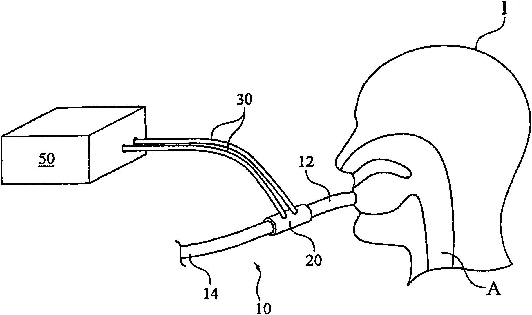
[0021] refer to figure 1 , depicts breathing catheter 10 . In an exemplary embodiment of the invention, breathing conduit 10 is a breathing circuit (also referred to as a patient circuit) that includes a patient interface at one end 12 . The patient interface is any device, invasive or non-invasive, suitable for coupling a breathing conduit into fluid communication with the airway A of the individual 1, such as an endotracheal tube, endotracheal tube, nasal mask, nasal / mask, or nasal cannula. As depicted, one end 12 of the breathing conduit 10 is placed in communication with the airway A, while the other end 14 of the breathing conduit is open to a source of gas to be inhaled by the individual I. The present invention contemplates that the source or gas may be such as known in the art, oxygen sources, ventilators, pressure support systems (e.g., CPAP, bilevel pressure support systems, auto-titration pressure support systems), other gas sources ( For example, Heliox) any gas ...


PUM


Abstract

An electro-pneumatic assembly (100) for use in a respiratory measurement system that includes a housing (210) having a plurality of channels (212, 214, 216, 218) defined therein and a plurality of walls (224) forming a cavity (220). The housing includes an upper face (215), a lower face (225), and a plurality of apertures defined in the lower face of the housing. A cover (250) is affixed to the upper face of the housing to enclose the cavity thereby forming a chamber, and to enclose the channels thereby forming a plurality of conduits. A control component (320) is operatively coupled to at least one aperture in the plurality of apertures, and a measurement component (352, 354) is operatively coupled to at least one aperture in the plurality of apertures. This assembly provides a simple, robust component for managing the pneumatics of the respiratory measurement system.

Description

[0001] priority statement [0002] Pursuant to the terms of 35 U.S.C. §119(e), this application claims the benefit of U.S. Provisional Patent Application No. 60 / 968,732, filed August 29, 2007, and pursuant to the terms of 35 U.S.C. §120 / 365, this application Claims the benefit of US Application No. 12 / 196,358, filed August 22, 2008. technical field [0003] The present invention relates to an integrated electro-pneumatic assembly for use in a respiration measurement system and a method of assembling the same. Background technique [0004] Respiratory flow and pressure measurements in the monitoring of the physical condition of athletes and other individuals during the administration of anesthesia, in the intensive care setting, and before or during the course of training programs and other medical testing provide useful information for assessing cardiorespiratory function and breathing circuit integrity valuable information. Many different technologies have been applied to...

Claims


Application Information

Patent Timeline
Patent Type & Authority Applications(China)
IPC IPC(8): A61B5/08
CPCA61B5/0876A61B2562/0247A61B5/087
Inventor D·斯坎波利
Owner PHILIPS RS NORTH AMERICA LLC
Why Eureka
Try Eureka