Spiral welded pipe weld seam probe frame

A technology of spiral welded pipe and probe holder, which is applied in the direction of material analysis using sound wave/ultrasonic wave/infrasonic wave, solid state analysis using sound wave/ultrasonic wave/infrasonic wave, measuring device, etc. Eliminate and other problems to achieve the effect of improving defect detection rate, reducing flaw detection error, and simple structure

Active Publication Date: 2010-07-28
鞍山长风无损检测设备有限公司
View PDF7 Cites 13 Cited by
  • Summary
  • Abstract
  • Description
  • Claims
  • Application Information

AI Technical Summary

Problems solved by technology

[0002] At present, the use of ultrasonic automatic flaw detection is a very economical and effective means to inspect and control the weld quality of spiral submerged arc welded pipes, and it is also a necessary detection method for the production of important pipelines in recent years. There are two rows of weld probes arranged symmetrically on the side. The weld probe emits ultrasonic waves, which are reflected back when they encounter defects in the steel pipe, and are received by this probe or other probes. After the signals are analyzed by the control system, the shape of the defect is drawn. All weld probes They are all installed on a weld probe frame, which moves along the weld seam under the control of the weld seam tracking system. The frame is mostly designed as a space plate or connecting rod structure. When the diameter and wall thickness of the spiral tube change, the distance between the probes and the lifting angle must be adjusted. At present, the structure of the welded probe frame can only be adjusted simply. Therefore, the probe It cannot be guaranteed to be completely bridged with the outer wall of the steel pipe, thereby increasing the flaw detection error, and it is difficult to eliminate

Method used


Image

  • Spiral welded pipe weld seam probe frame
  • Spiral welded pipe weld seam probe frame
  • Spiral welded pipe weld seam probe frame

Examples


Embodiment Construction

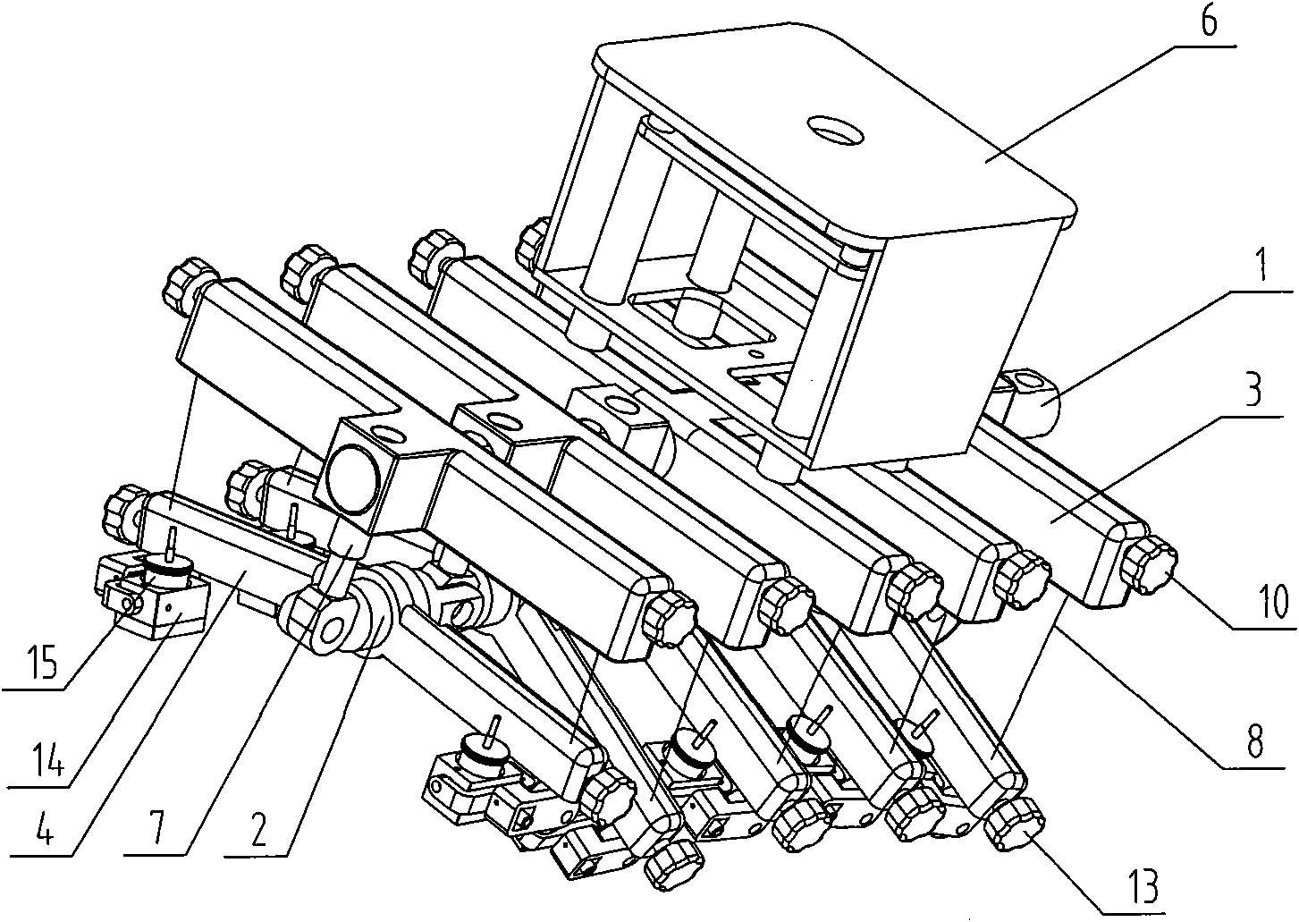
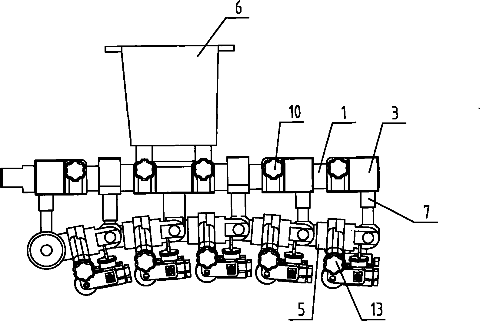
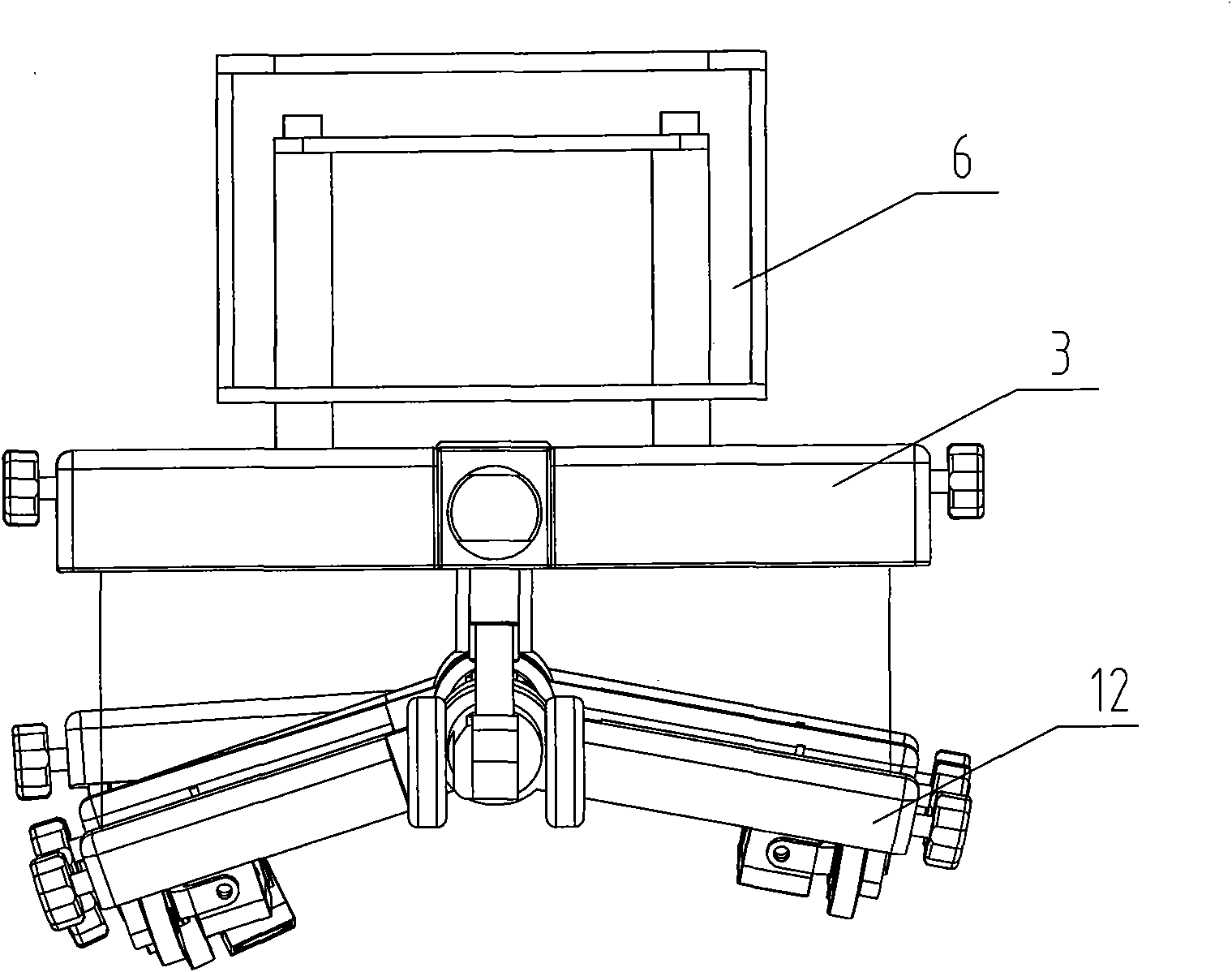
[0015] The specific embodiment of the present invention will be further described below in conjunction with accompanying drawing:

[0016] See figure 1 , figure 2 , image 3 , Figure 4 , Figure 5 , a spiral welded pipe weld probe frame, comprising a rigid main shaft 1, a flexible main shaft 2, a fixed wing 3, and a swinging wing 4, the rigid main shaft 1 and the flexible main shaft 2 are arranged in parallel up and down, and a plurality of fixed wings 3 are arranged in series Connected to the rigid main shaft 1, the flexible main shaft 2 is composed of a plurality of main shaft joints 5 connected end to end. The radian of the flexible main shaft 2 is manually adjusted by the arc adjusting screw 7, the adjustment range is large, and the adjustment is flexible. The swing wing 4 is arranged under the fixed wing 3, which is beneficial to ensure the correct shape of the adjustment. Stable, the end of the swinging wing 4 is connected with the end of the fixed wing 3 through ...


PUM


Abstract

The invention relates to a spiral welded pipe weld seam probe frame which comprises a rigid spindle, a flexible spindle, fixed wing plates and swing wing plates; the rigid spindle and the flexible spindle are arranged up and down in parallel; the plurality of fixed wing plates are sequentially connected on the rigid spindle serially; the flexible spindle comprises a plurality of spindles which are connected end to end through joints; each spindle joint is provided with a pair of swing wing plates; the spindle joints and the fixed wing plates and the rigid spindles are connected by radian regulating screw rods; the swing wing plates are arranged below the swing wing plates; and both side ends of each swing wing plate are respectively connected with both side ends of each fixed wing plate through traction mechanisms. The spiral welded pipe weld seam probe frame has the benefits that: (1) the flexible spindle is adopted, so that a probe and a weld seam can be fully closed, so as to reduce error; (2) the rigid spindle and the flexible spindle are arranged up and down in parallel, and the adjusted shapes are stable; (3) the radian of the flexible spindle is manually regulated by the radian regulating screw rod, and the adjustment is flexible; and (4) is structure is applicable to a plurality of probe models, and the defect defection rate can be greatly improved.

Description

technical field [0001] The invention relates to the field of ultrasonic non-destructive flaw detection, in particular to a spiral welded pipe weld seam probe frame. Background technique [0002] At present, the use of ultrasonic automatic flaw detection is a very economical and effective means to inspect and control the weld quality of spiral submerged arc welded pipes, and it is also a necessary detection method for the production of important pipelines in recent years. There are two rows of weld probes arranged symmetrically on the side. The weld probe emits ultrasonic waves, which are reflected back when they encounter defects in the steel pipe, and are received by this probe or other probes. After the signals are analyzed by the control system, the shape of the defect is drawn. All weld probes They are all installed on a weld probe frame, which moves along the weld seam under the control of the weld seam tracking system. The frame is mostly designed as a space plate or ...

Claims


Application Information

Patent Timeline
Patent Type & Authority Applications(China)
IPC IPC(8): G01N29/24G01N29/04
Inventor 刘忠魁
Owner 鞍山长风无损检测设备有限公司
Why Eureka
Try Eureka