Transverse wave detection method for defects of spiral weld steel pipe body and flaw detection apparatus used in same

A technology of spiral welding seam and detection method, which is applied in the direction of measuring device, analysis of solids using sonic/ultrasonic/infrasonic waves, and material analysis using sonic/ultrasonic/infrasonic waves, etc. The outer wall of the steel pipe cannot guarantee the bridging and other problems, so as to achieve the effect of good bridging, reducing flaw detection error and convenient adjustment.

Active Publication Date: 2014-11-26
CNPC BOHAI EQUIP MFG +1
View PDF5 Cites 0 Cited by
  • Summary
  • Abstract
  • Description
  • Claims
  • Application Information

AI Technical Summary

Problems solved by technology

[0005] In the process of automatic flaw detection, in order to ensure that all the weld probes fall on the steel pipe and accurately bridge the outer wall of the steel pipe, the weld probe holder is mostly designed as a space plate shape or a connecting rod structure. When the diameter and wall thickness of the spiral pipe change, the probe should be adjusted The distance between the probe and the lifting angle, the current structure of the weld probe frame can only be adjusted for a simple distance, so the probe and the outer wall of the steel pipe cannot be guaranteed to be completely bridged, thereby increasing the flaw detection error, and it is difficult to eliminate

Method used


Image

  • Transverse wave detection method for defects of spiral weld steel pipe body and flaw detection apparatus used in same
  • Transverse wave detection method for defects of spiral weld steel pipe body and flaw detection apparatus used in same
  • Transverse wave detection method for defects of spiral weld steel pipe body and flaw detection apparatus used in same

Examples


Embodiment Construction

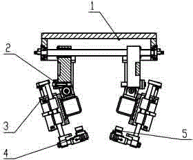
[0027] According to attached figure 1 It can be seen that the present invention specifically relates to a shear wave detection method and flaw detection device for spiral welded steel pipe body defects. The detection method uses a shear wave probe and a special layout method to realize the detection of steel pipe body defects with spiral welds.

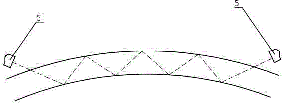
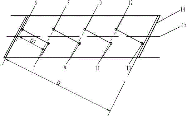
[0028] The detection method in the present invention includes the following steps: first, more than one set of shear wave probes are arranged between two adjacent welds on the surface of the steel pipe body, and one set of shear wave probes includes a transmitting probe and a receiving probe, wherein the transmitting probe is used to transmit shear waves , the receiving probe is used to receive the shear wave emitted by the transmitting probe, the connection line between the transmitting probe and the receiving probe in each group of shear wave probes is perpendicular to the weld seam, and the direction of the transmitting probe and th...


PUM


Abstract

The invention discloses a transverse wave detection method for defects of a spiral weld steel pipe body and a flaw detection apparatus used in the same, belonging to the field of ultrasonic nondestructive flaw detection. According to the detection method, defects on the surface of a steel pipe and defects of welds are detected through transverse wave probes which are arranged between two spiral welds and perpendicular to the welds, and it is guaranteed that a detection area reaches 100%. The flaw detection apparatus comprises a freely elevating probe rack and basic detection units; a cross bar is fixedly arranged in the probe rack, a pair of the basic detection units are sleeved on and connected with the cross bar; the basic detection unit comprises a transverse adjusting means, a probe elevating means, a fixed base and a probe, wherein one end of the transverse adjusting means is sleeved on and connected with the cross bar, the other end of the transverse adjusting means is connected with the probe elevating means, telescoping connecting rods are arranged in the probe elevating means, and the end of the connecting rods is connected with the fixed base used for fixing the probe. According to the invention, distances among and elevating height of the probes can be flexibly adjusted, complete overlapping of the probes and the welds is guaranteed, flaw detection errors are reduced, and a detection level is improved.

Description

technical field [0001] The invention relates to a shear wave detection method for defects of a spiral welded steel pipe body and a flaw detection device thereof, which belong to the field of ultrasonic nondestructive flaw detection and are used in the ultrasonic detection process of a base material of a spiral seam submerged arc welded pipe. Background technique [0002] In order to ensure the quality of submerged arc welded steel pipes, the use of ultrasonic automatic flaw detection is a very economical and effective means to inspect and control the weld quality of spiral submerged arc welded pipes, and it is also a necessary detection method for the production of important pipelines in recent years. [0003] The principle of automatic flaw detection for spiral pipes is that two rows of weld probes are arranged symmetrically on both sides of the space helical curve weld. After the control system analysis, the defect shape is delineated. [0004] In general production pract...

Claims


Application Information

Patent Timeline
Patent Type & Authority Patents(China)
IPC IPC(8): G01N29/04G01N29/265
Inventor 孙志敏安晓军孙少卿马兴华
Owner CNPC BOHAI EQUIP MFG
Why Eureka
Try Eureka