Anti-leakage butterfly valve

A technology of anti-leakage and butterfly valves, which is applied in the direction of lifting valves, valve details, valve devices, etc., can solve the problems of untimely detection and small leakage of sanitary butterfly valves, and achieve the effect of flexible and convenient assembly, easy detection, and flexible rotation

Inactive Publication Date: 2010-08-04
浙江远安流体设备有限公司
View PDF1 Cites 7 Cited by
  • Summary
  • Abstract
  • Description
  • Claims
  • Application Information

AI Technical Summary

Problems solved by technology

[0004] For this reason, the technical problem to be solved by the present invention lies in the problem that the sanitary butterfly valve in the prior art cannot be detected ...

Method used


Image

  • Anti-leakage butterfly valve
  • Anti-leakage butterfly valve
  • Anti-leakage butterfly valve

Examples


Embodiment Construction

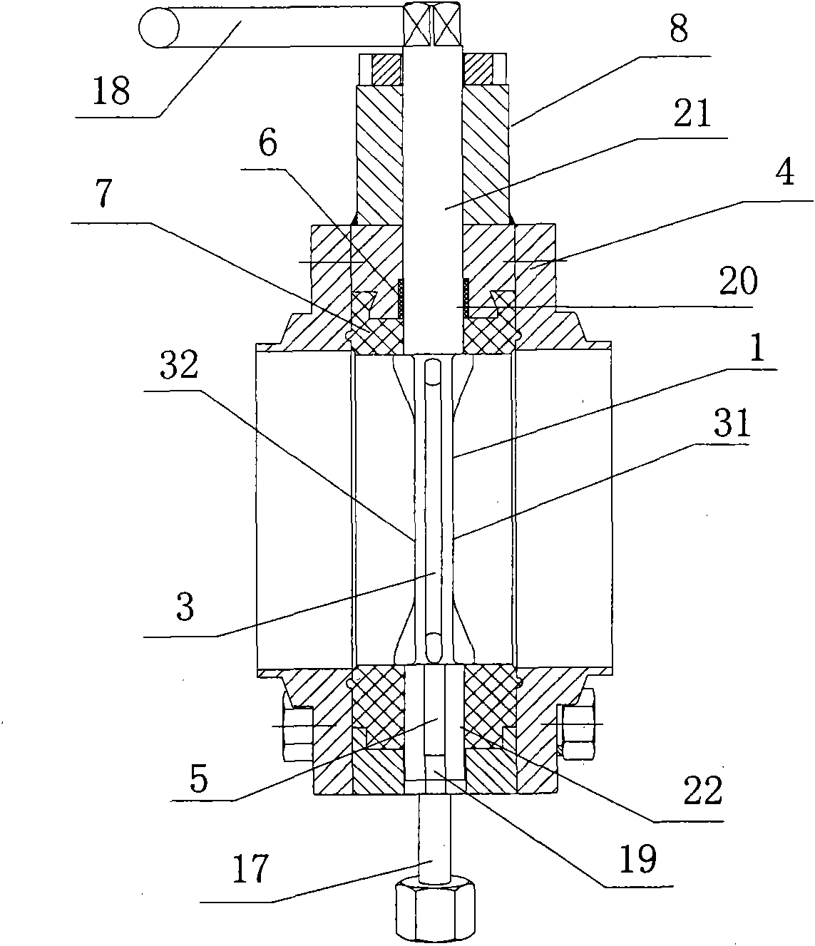
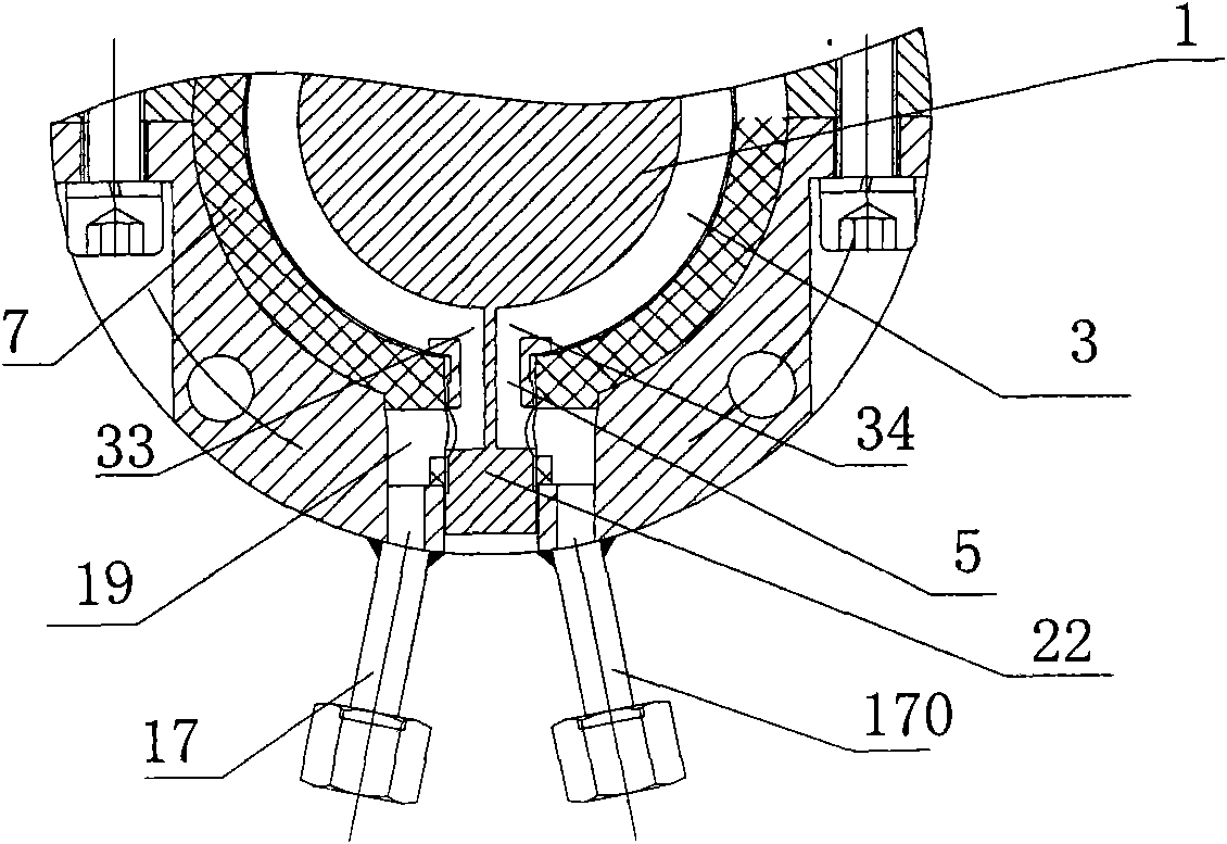
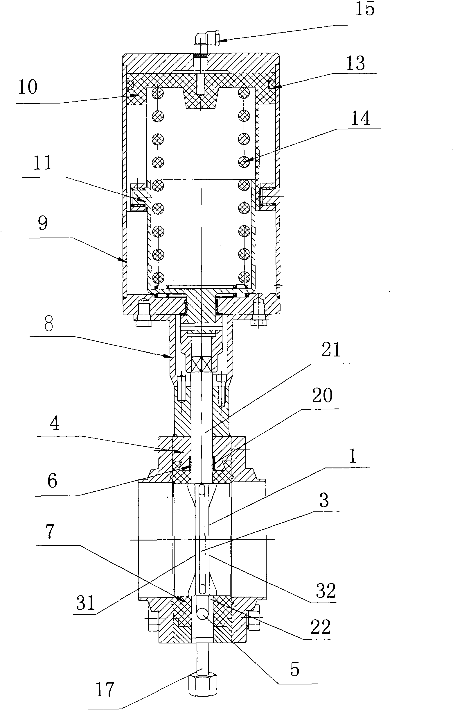
[0022] figure 1 A specific embodiment of the anti-leakage butterfly valve according to the present invention is given, Example 1, an anti-leakage butterfly valve, comprising: a valve body 4, an inner cavity is formed in the valve body 4; a butterfly plate 1, The butterfly plate 1 is arranged in the inner cavity of the valve body 4, and when the butterfly plate 1 is closed, its two end faces 31, 32 form a seal with the inner cavity; the valve shaft, the valve shaft and the The butterfly plate linkage, the valve shaft is arranged symmetrically along the radial direction of the butterfly plate, and is divided into two parts: the upper valve shaft 21 and the lower valve shaft 22, and the butterfly plate 1 is installed in the valve body 4 through the valve shaft In the cavity; the actuator, the actuator is connected with the upper valve shaft 21, the opening and closing of the butterfly plate 1 is realized by controlling the rotation of the upper valve shaft 21, and the actuator is...


PUM


Abstract

The invention relates to an anti-leakage butterfly valve which comprises a valve body, a butterfly plate, a valve shaft and an executing mechanism. An inner cavity is formed in the valve body. The butterfly plate is arranged in the inner cavity of the valve body. When the butterfly valve is closed, two end surfaces respectively form seal with the inner cavity. The valve shaft is linked with the butterfly plate, is symmetrically arranged along the radial direction of the butterfly plate, and is separated into an upper shaft valve and a lower shaft valve. The executing mechanism is connected with the upper valve shaft, and controls the rotation of the upper valve shaft to open and close the butterfly plate. The side wall of the butterfly plate is provided with a groove in the circumferential direction, the groove is communicated with a flowing passage in the lower valve shaft, and the flowing passage is communicated with the outside through a guide pipe on the valve body. The invention solves the technical problem that the leakage of the sanitary butterfly valve in the prior art can not be detected in time when the leakage amount is small, and is especially suitable for the sanitary food industry.

Description

technical field [0001] The invention relates to a butterfly valve, in particular to an anti-leakage butterfly valve. Background technique [0002] Butterfly valve, also known as flap valve, is a regulating valve with simple structure, and it can also be used for switch control of low-pressure pipeline medium. The opening and closing part of the butterfly valve is a disc-shaped butterfly plate, which rotates around its own axis in the valve body, so as to achieve the purpose of opening and closing or adjustment. Butterfly valves are mainly used as cut-off valves, and can also be designed as valves with adjustment or cut-off and adjustment functions. [0003] In the prior art, a butterfly valve generally includes a valve body, a disc plate, a valve shaft and an actuator. The butterfly plate is arranged in the valve body and cooperates with the inner cavity of the valve body to form a sealing mechanism when it is closed. The butterfly plate and the valve shaft are linked. The...

Claims


Application Information

Patent Timeline
IPC IPC(8): F16K1/22F16K1/226F16K1/36F16K1/32F16K27/02F16K31/12
Inventor 邵显安
Owner 浙江远安流体设备有限公司
Why Eureka
Try Eureka