Current-limiting and controlling method of active damping of current-limiting and storage circuit

An energy storage circuit and current limiting control technology, which is applied to emergency protection circuit devices for limiting overcurrent/overvoltage, circuit devices, usage of superconductor elements, etc. and other problems, to achieve the effects of high controllability, prevention of overcurrent faults, and strong robustness

Inactive Publication Date: 2013-07-03
INST OF ELECTRICAL ENG CHINESE ACAD OF SCI
View PDF1 Cites 0 Cited by
  • Summary
  • Abstract
  • Description
  • Claims
  • Application Information

AI Technical Summary

Problems solved by technology

Although this method does not need the output voltage of the voltage source inverter to control the fault state, it needs to add a bulky and expensive current-limiting inductor. At the same time, due to the influence of the current-limiting reactor, when the grid voltage drops, the voltage source The converter not only needs to compensate the sag voltage of the power grid, but also needs to compensate the voltage of the current-limiting reactor, and the function of voltage compensation is relatively weak.

Method used


Image

  • Current-limiting and controlling method of active damping of current-limiting and storage circuit
  • Current-limiting and controlling method of active damping of current-limiting and storage circuit
  • Current-limiting and controlling method of active damping of current-limiting and storage circuit

Examples


Embodiment Construction

[0025] The present invention will be further described below with reference to the drawings and specific embodiments.

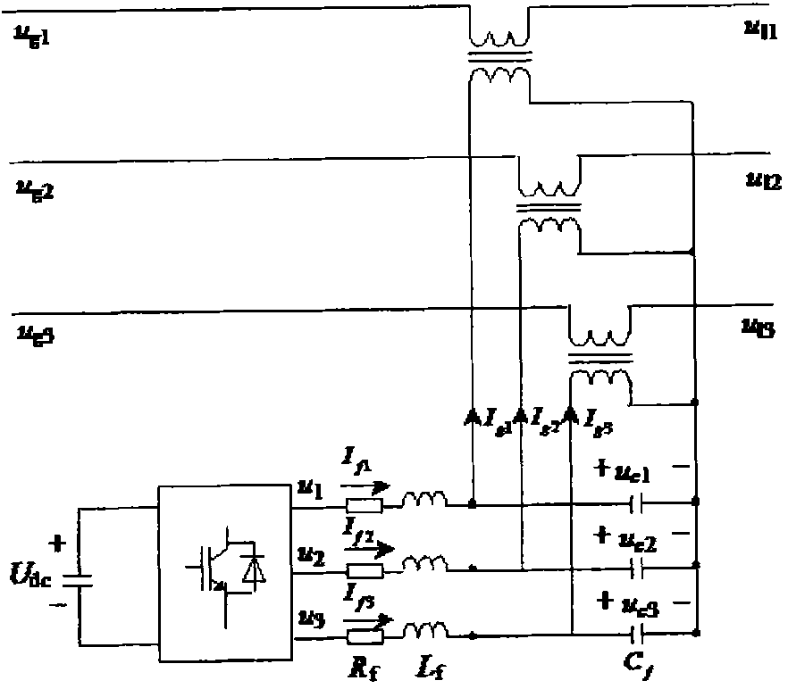
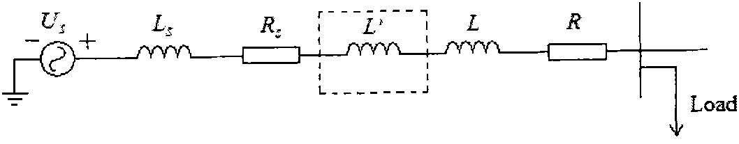
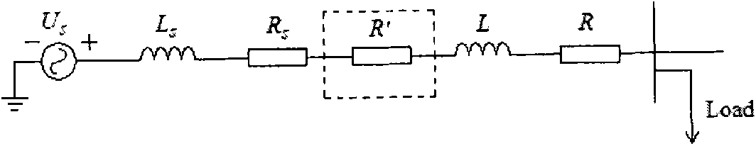
[0026] Image 6 Middle U s Is the system voltage, L s Is the system inductance, R s Is the system resistance, L is the line inductance, R is the line resistance, C is the filter capacitor, and R′ is the virtual inductance) Figure 7 This is the circuit topology of Embodiment 1 of the present invention. Such as Figure 7 Shown: the first switch S1, the second switch S2, the third switch S3, the fourth switch S4, the fifth switch S5, and the sixth switch S6 form a first current source converter CSC1; the cathode of the first switch S1 and the first switch S1 The anodes of the four switches S4 are connected to form the first AC connection point PA1; the first switch S1 and the fourth switch S4 form the first half bridge HB1 of the first current source inverter; the cathode of the second switch S2 is connected to the fifth switch S5 The anode of S3 is connected to f...


PUM


Abstract

The invention discloses a current-limiting and controlling method of active damping of a current-limiting and tank circuit. The output of a first half bridge (HB1) of a first current source inverter (CSC1) has the same phase with a first filter capacitor (C1) and the current with the amplitude of 1 / R; the output of a second half bridge (HB2) of the first current source inverter (CSC1) has the same phase with a second filter capacitor (C2) and the current with the amplitude of 1 / R; the output of a third half bridge (HB3) of the first current source inverter (CSC1) has the same phase with a third filter capacitor (C3) and the current with the amplitude of 1 / R; or the output of the first current source inverter (CSC1) has the same phase with the first filter capacitor (C1) and the current with the amplitude of 1 / R; the output of a second current source inverter (CSC2) has the same phase with the second filter capacitor (C2) and the current with the amplitude of 1 / R; and the output of a third current source inverter (CSC3) has the same phase with the third filter capacitor (C3) and the current with the amplitude of 1 / R. In the invention, open-loop control is needed only and the response speed is nearly instantaneous.

Description

Technical field [0001] The invention relates to a control method of a current-limiting energy storage circuit. Background technique [0002] With the rapid development of the national economy, the society’s demand for electricity continues to increase, which has led to the continuous development of the power system. The continuous increase in the capacity of single machines and power plants, the capacity of substations, and urban and central loads has resulted in the interconnection of power systems. The level of short-circuit current in high-level power grids continues to increase, and short-circuit faults are becoming more and more destructive to the power system and its connected electrical equipment. Moreover, while the demand for electric energy is increasing, people have also put forward higher requirements for power quality, power supply reliability and safety. However, the transient stability problem of large power grids is more prominent. One of the most important reaso...

Claims


Application Information

Patent Timeline
Patent Type & Authority Patents(China)
IPC IPC(8): H02H9/02
CPCY02E40/69Y02E40/60
Inventor 郭文勇肖立业戴少涛张志丰
Owner INST OF ELECTRICAL ENG CHINESE ACAD OF SCI
Why Eureka
Try Eureka