
Transport roller, transport unit, and printing apparatus

A technology of conveying unit and conveying roller, applied in conveying unit, printing device, conveying roller field, can solve the problems of conveying speed, conveying fluctuation, conveying fluctuation, etc.

Active Publication Date: 2010-08-18
SEIKO EPSON CORP
View PDF1 Cites 1 Cited by
  • Summary
  • Abstract
  • Description
  • Claims
  • Application Information

AI Technical Summary

Problems solved by technology

In addition, when the groove is in contact with the paper (recording medium) during paper feeding, different contact resistance will be generated when the other surface is in contact with the paper. As a result, the conveying speed will change and cause conveying fluctuations.
In addition, in so-called inkjet printers that discharge fine liquid droplets to form images, extremely high paper feeding accuracy is required, so the occurrence of feeding fluctuations due to these grooves is particularly a problem.

Method used


Image

  • Transport roller, transport unit, and printing apparatus
  • Transport roller, transport unit, and printing apparatus
  • Transport roller, transport unit, and printing apparatus

Examples


Embodiment Construction

[0061] The present invention will be described in detail below with reference to the drawings. In addition, in each of the drawings used in the following description, the ratio of each member is appropriately changed in order to make each member have a recognizable size.

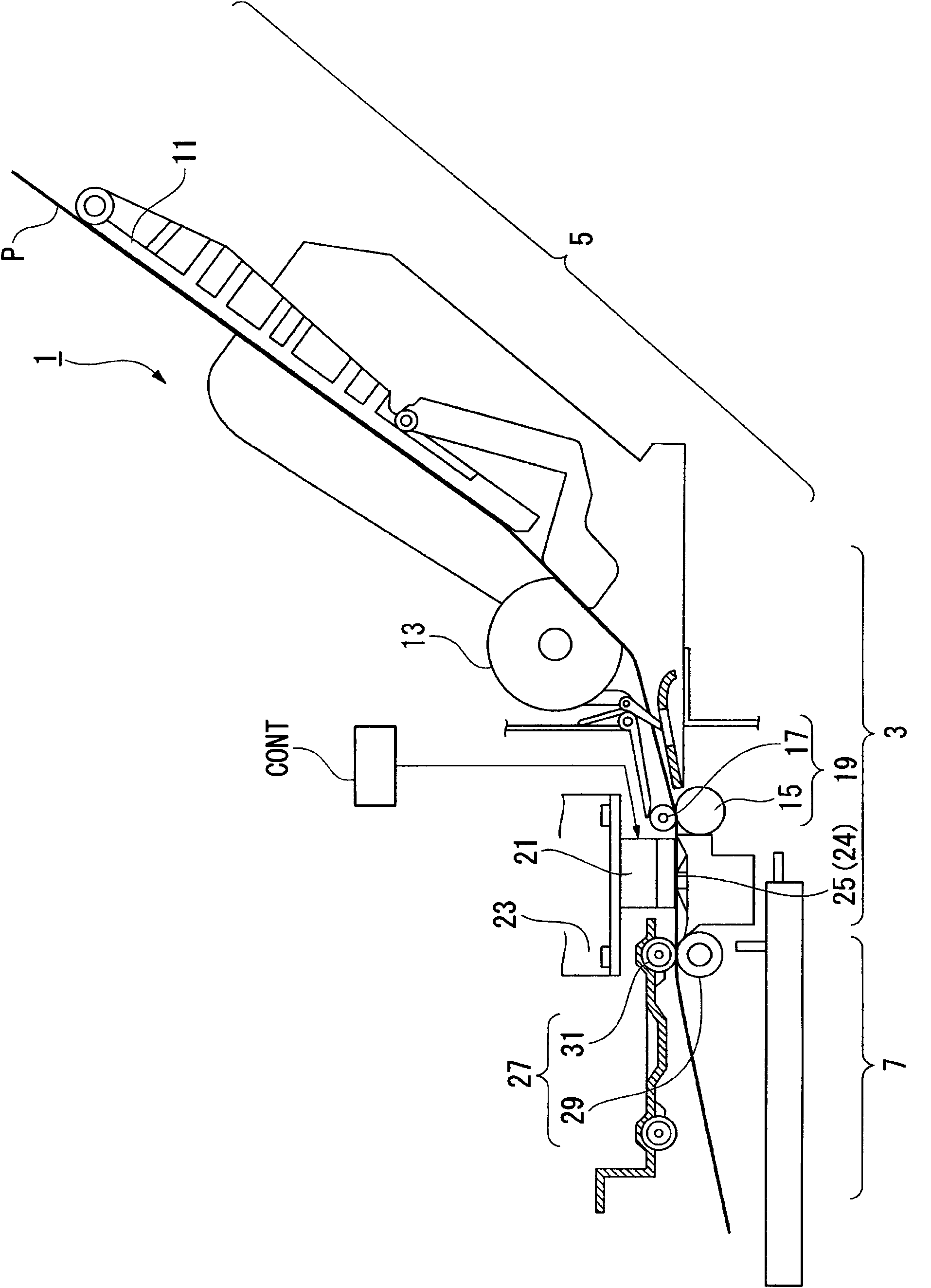
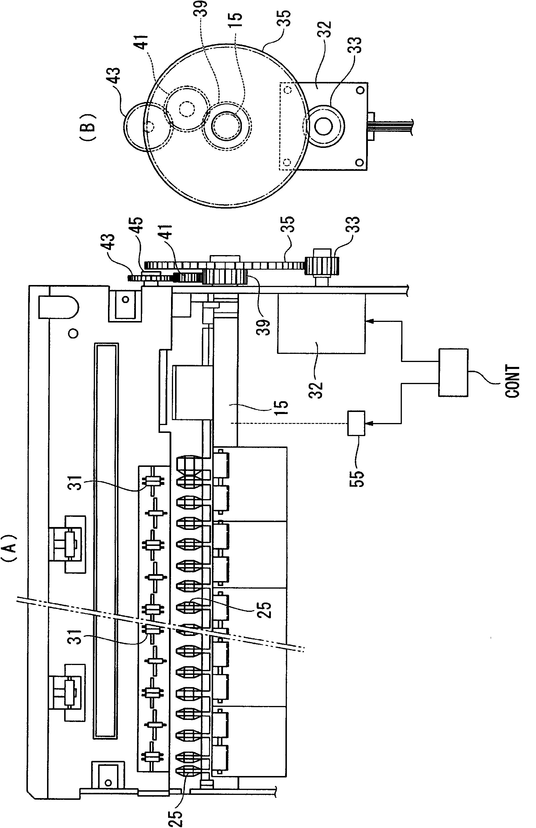
[0062] First, refer to figure 1 , figure 2 A description will be given of a printing device having the transport roller of the present invention. and, figure 1 Is a side cross-sectional view of the printing device (inkjet printer) with the conveying unit of the present invention, figure 2 (A) is a top view of the conveying unit part of the printing device, figure 2 (B) is a side view of the drive system of the printing device.

[0063] in figure 1 The symbol 1 is an inkjet printer in an embodiment of the printing device of the present invention. The inkjet printer 1 is configured to include a printer main body 3, a paper feed section 5 provided on the upper rear side of the printer main body 3, and a paper di...


PUM


Abstract

A transport roller includes: a roller body of which a pair of end surfaces face each other by a press work so as to be in a cylindrical shape; and a high friction layer which contains inorganic particles and is provided on a surface of the roller body. Here, the roller body is provided with a joining portion which is formed by separating the pair of end surfaces. In addition, an average particle diameter of the inorganic particle is larger than a distance between the pair of the end surfaces of the roller body on an outer peripheral surface side thereof.

Description

Technical field [0001] The invention relates to a conveying roller, a conveying unit, and a printing device. Background technique [0002] Various printers have been provided as printing devices in the past. In this type of printer, recording media such as paper are transported to the printing section through a transport roller (paper feed roller) and a driven roller, where it passes through the paper discharge roller (drive roller) and its driven roller (squeeze roller) after printing. ギザロ一ラ) eject the recording medium. [0003] In this type of printer, the paper is clamped between the conveying roller and the driven roller, and the paper is rotated and driven in this state to move the paper in the sub-scanning direction orthogonal to the moving direction of the carriage. Therefore, the paper is transported to the recording position with high precision, and then sequentially fed in according to the printing speed, which requires a high transport force. [0004] Therefore, in order...

Claims


Application Information

Patent Timeline
Patent Type & Authority Applications(China)
IPC IPC(8): B41J13/076B21C37/10
CPCB41J13/076B41N7/00B41N2207/10B21C37/15B41N2207/02F16C13/00B65H2404/1351B65H2401/115C23C24/04B65H2404/531B65H2402/80B65H27/00B65H2404/13B65H2401/11
Inventor 齐藤功一大野克德小泽健司
Owner SEIKO EPSON CORP
Features
  • Generate Ideas
  • Intellectual Property
  • Life Sciences
  • Materials
  • Tech Scout
  • Unparalleled Data Quality
  • Higher Quality Content
  • 60% Fewer Hallucinations
Learn More