

Direct-driven front and back wind wheel contra-rotating wind driven generator
A technology of whirling wind power generator and rear wind wheel, which can be applied to wind power generators, wind power generator combinations, wind power generators that are consistent with the wind direction, etc., and can solve the problems of low energy utilization efficiency and the like
- Summary
- Abstract
- Description
- Claims
- Application Information
AI Technical Summary
Problems solved by technology
Method used
Image

Examples
Embodiment Construction
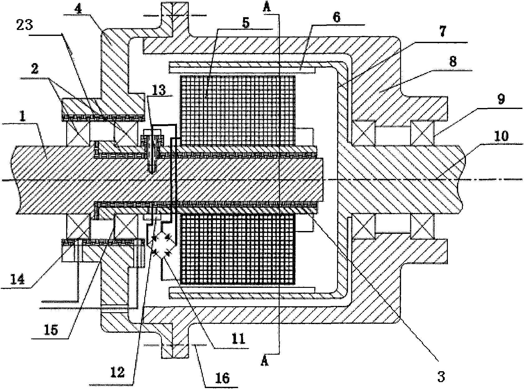
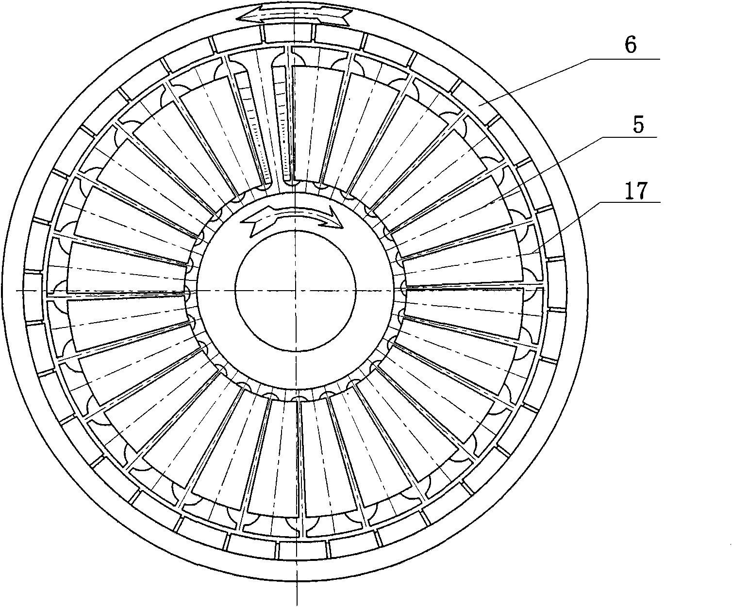
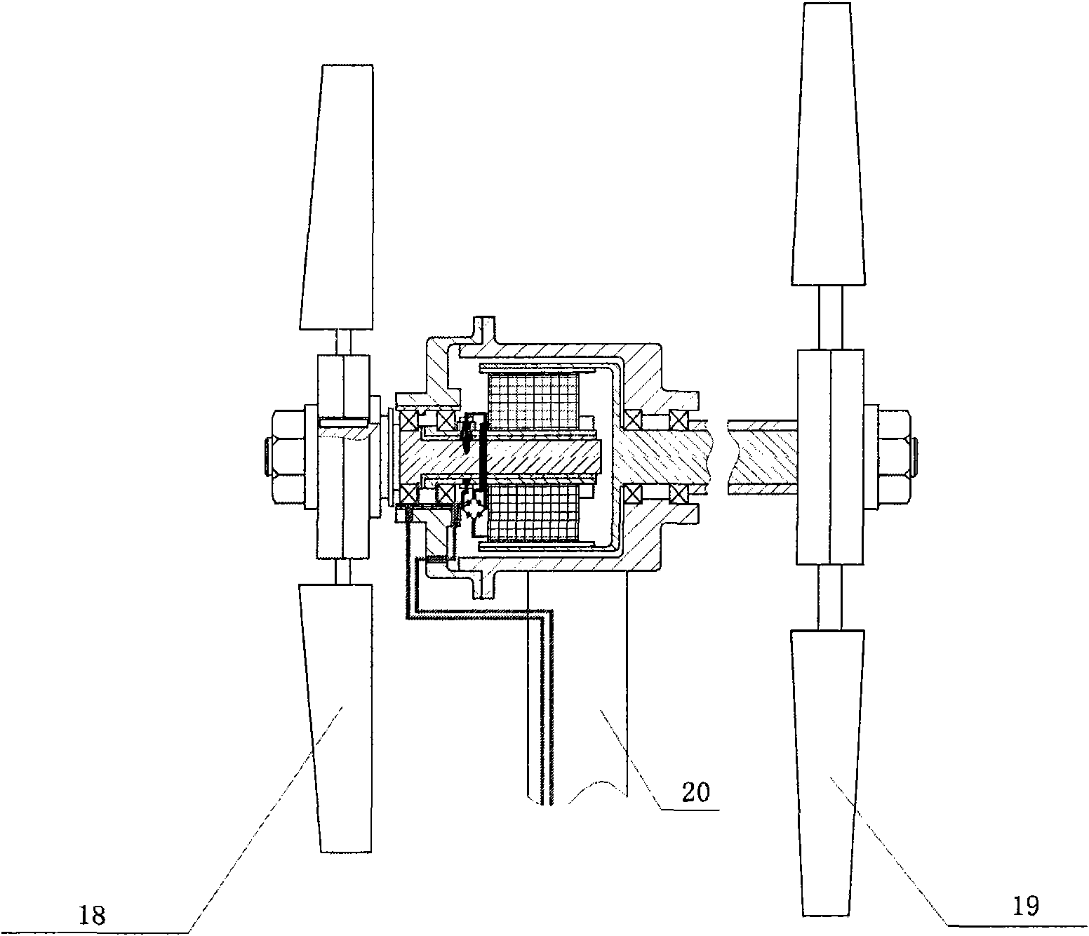
[0014] refer to Figure 1~3 . The direct drive type front and rear wind rotor counter-rotating wind generator includes a first wind rotor 18, a second wind rotor 19, a front input shaft 1, a rear input shaft 10, an inner rotor 5, an outer rotor 7, a first bearing 2, a second Two bearings 9 and rare earth permanent magnets 6, one end of the front input shaft 1 is fixedly connected to the first wind wheel 18, and the other end is connected to the coil winding to form the inner rotor 5, the first wind wheel 18 absorbs incoming wind power to drive the front input shaft 1 of the generator Rotate clockwise; the front input shaft 1 is supported by the first bearing 2 fixed at the end of the front box cover 4; the front input shaft 1 starts from the middle of the high voltage collector ring 14 and the low voltage collector ring 15 to its end by the first The bushing 3 is wrapped; the coil windings are wound on 28 silicon steel sheets 17 with a concave-convex structure to form 28 coil...
PUM
 Abstract
Description
Claims
Application Information