
Cleaner

A technology of cleaners and bottom plates, which is applied in the field of cleaners and can solve problems such as impracticality

Inactive Publication Date: 2010-09-08
黄伟伟
View PDF0 Cites 0 Cited by
  • Summary
  • Abstract
  • Description
  • Claims
  • Application Information

AI Technical Summary

Problems solved by technology

[0002] There are many kinds of cleaning tools and various structures, but they are not very practical

Method used


Image

  • Cleaner
  • Cleaner

Examples


Embodiment Construction

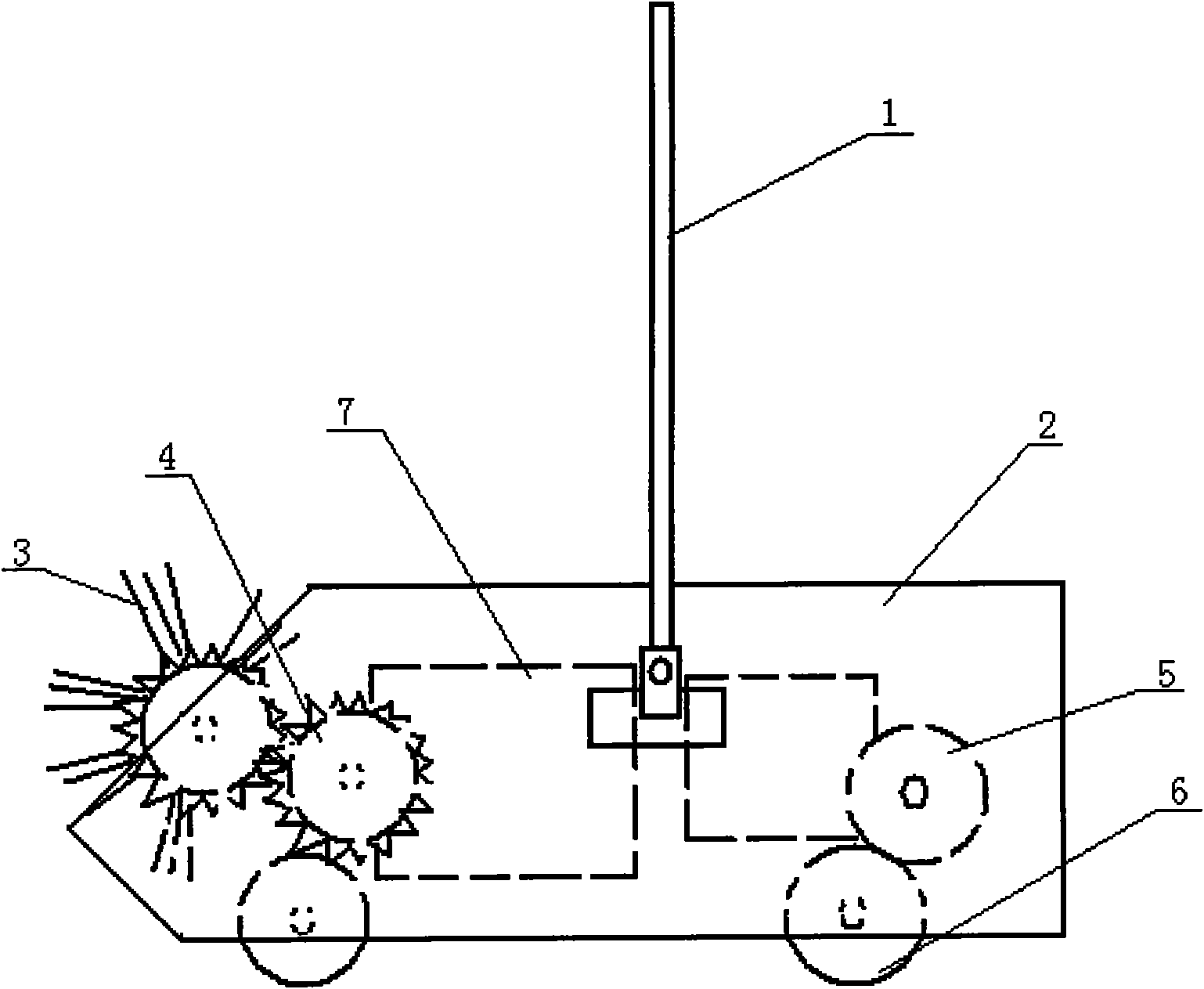
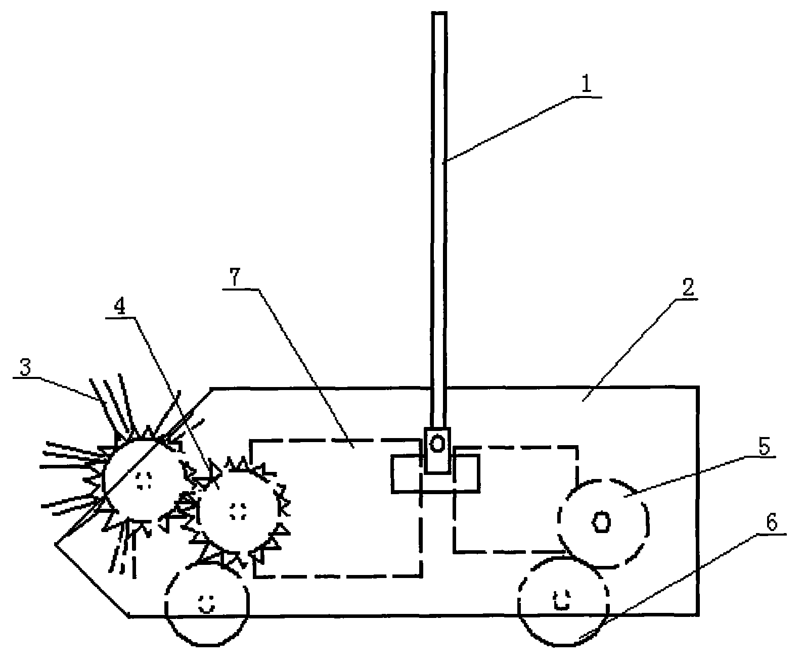
[0010] Such as figure 1 As shown, a cleaner comprises a hand lever 1 and a bottom plate 2, the hand lever 1 is movably connected with the bottom plate 2, and the bottom plate 2 is provided with a transmission gear 4, a rotating sponge shaft 5 and pulleys 6 each, and the pulleys 6 are connected with the transmission gear respectively. 4 links to each other with rotating sponge shaft 5, and hairbrush 3 is on transmission gear 4, and rotating sponge shaft 5 is fixed with sponge, and base plate 2 is provided with two storehouses 7 of dress rubbish.

[0011] When in use, the hand lever 1 can rotate around the bottom plate 2, and the direction can be adjusted at will. The pulley 6 on the bottom plate 2 drives the transmission gear 4 and the rotating sponge shaft 5 to move respectively, and the brush 3 and the sponge on the transmission gear 4 and the rotating sponge shaft 5 can The rubbish on the ground is swept into the bin 7 of dress rubbish.


PUM


Abstract

The invention discloses a cleaner comprising a handspike and a baseboard, wherein the handspike is movably connected with the baseboard, the baseboard is provided with a transmission gear, a transmission sponge shaft and pulleys, the pulleys are respectively connected with the transmission gear and the transmission sponge shaft, a brush is arranged on the transmission gear, sponge is fixed on the transmission sponge shaft, and the baseboard is provided with two bins for containing garbage. Because of the above structure, the pulleys slide to drive the transmission gear and the transmission sponge shaft to move, the brush and the sponge on the transmission gear and the transmission sponge shaft can sweep garbage on the ground into the bins for containing garbage to reach the purpose of cleaning the ground.

Description

technical field [0001] The invention relates to an improvement of a cleaning tool, especially a cleaner. Background technique [0002] Present cleaning tools are of a great variety and have various structures, but they are not all very practical. Contents of the invention [0003] The object of the present invention is to provide a practical cleaner. [0004] The object of the present invention is achieved like this: a kind of cleaning device comprises hand bar and base plate, and hand bar is movably connected with base plate, and base plate is provided with transmission gear, rotating sponge shaft and each pulley, and pulley is connected with transmission gear and rotating sponge respectively. The shafts are connected, the hair brush is on the transmission gear, the sponge is fixed on the rotating sponge shaft, and two bins for containing garbage are arranged in the base plate. [0005] Due to the adoption of the above structure, the sliding of the pulley can drive the ...

Claims


Application Information

Patent Timeline
Patent Type & Authority Applications(China)
IPC IPC(8): A47L11/00A47L11/33A47L11/24
Inventor 黄伟伟
Owner 黄伟伟
Learn More