
Fluid flow valve

A fluid outlet and housing technology, applied in the field of fluid flow valves, can solve the problem of not being able to continuously release a small amount of air, and achieve the effects of cheap manufacturing, compact size and comprehensive design

Inactive Publication Date: 2010-09-08
A R I FLOW CONTROL ACCESSORIES LTD
View PDF3 Cites 0 Cited by
  • Summary
  • Abstract
  • Description
  • Claims
  • Application Information

AI Technical Summary

Problems solved by technology

However, with this dynamic valve, once the valve housing is filled with liquid and the float is pressed against the larger hole to seal the hole, the valve will only open again when the pressure in the housing drops to atmospheric pressure, so this Dynamic valves cannot be used to continuously release small amounts of air

Method used


Image

  • Fluid flow valve
  • Fluid flow valve
  • Fluid flow valve

Examples


Embodiment Construction

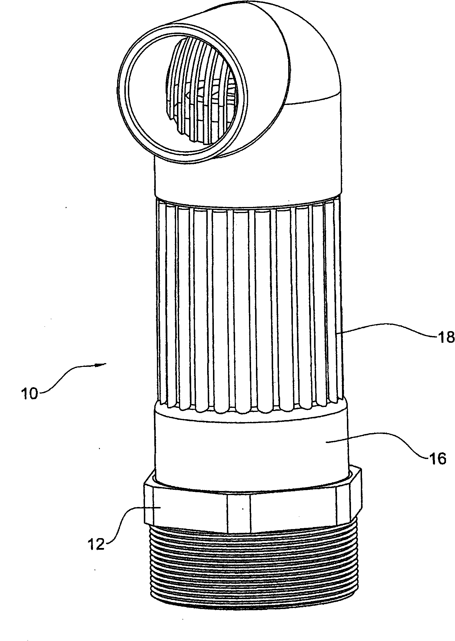
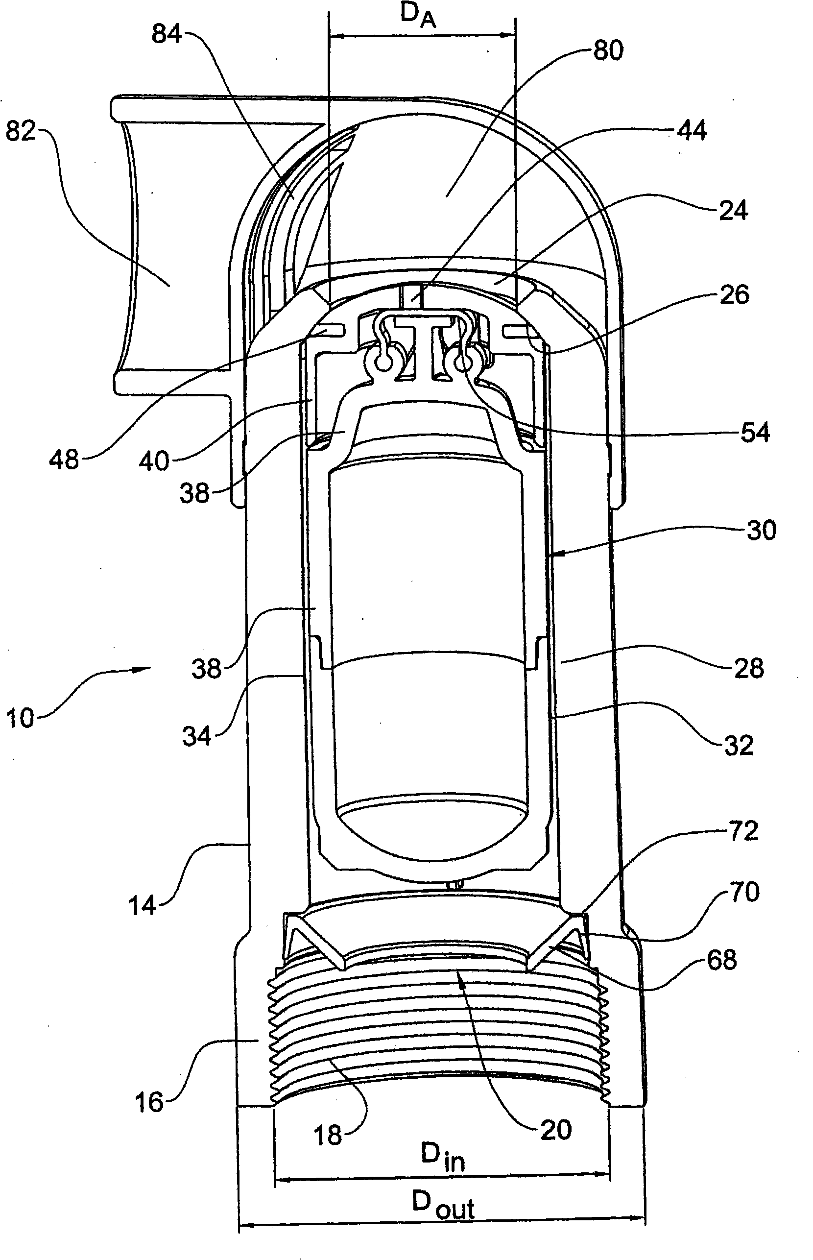
[0051] Note first the attached figure 1 and figure 2 , figure 1 and figure 2 A purge valve, referenced 10, according to the invention is shown. It should be noted that, figure 1 The valve assembly in figure 2 The threaded coupling 12 is not shown, which will be described in further detail below.

[0052] The valve 10 comprises a generally cylindrical housing 14 formed with a coupling portion 16 which in the present embodiment is an internal thread at 18 and also formed with a fluid inlet 20 and a fluid outlet 24 formed with a dynamic valve seat 26 at its bottom surface.

[0053] There are a number of radially extending axial ribs 28, two of which are figure 2 As can be seen in , the purpose is to limit the movement of the seal assembly 30 so that the seal assembly 30 moves axially but prevents it from rotating.

[0054] Seal assembly 30 includes a float member 32 including a cylindrical bottom 34 that is sealed by a float closure member 38, thereby collectively def...


PUM


Abstract

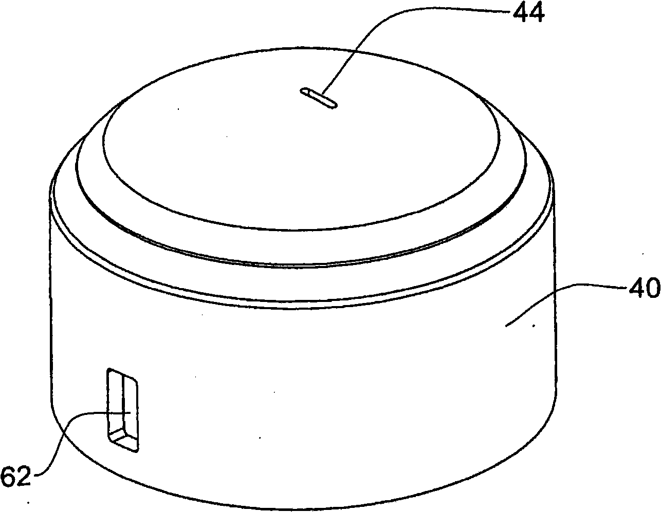
A gas purge valve (10) comprising a housing (14) formed with a fluid inlet (20) and a fluid outlet (24), said fluid outlet bounded by a kinetic valve seating (26), and a sealing assembly (30) comprising a float member (32) coaxially displaceable within the housing, and a sealing cap (40) coupled to said float member; the sealing cap being axially displaceable with respect to the float member between a first position in which it conjoins the float, and a second position in which it departs from the float; said sealing cap formed at an outside face thereof with a kinetic seal (48) fitted for sealing engagement of the kinetic valve seating, and an automatic valve aperture (44) formed in the sealing cap and bounded by an automatic valve seating (50); and an automatic sealing member (54) articulated at an upper end of the float member for sealing engagement of the automatic valve seating (50).

Description

technical field [0001] The present invention relates to a fluid flow valve adapted on the one hand to allow trapped air to escape in lesser or greater quantities and to allow air in to provide vacuum relief when the line is emptied. Background technique [0002] Such bleed valves are usually fitted in liquid piping (such as water mains distribution lines or other liquid supply lines) and are designed to ensure the release of air or other gases from the piping, thereby avoiding the creation of air locks, air locks interfere with the flow of liquids. [0003] For this purpose, two different types of purge valves are known. In these two types of bleed valves, the float is located in the housing, the lower end of the housing is connected to the pipe to be exhausted, and the upper end is provided with an exhaust hole. During normal operation with liquid flowing through the pipe, the housing fills with liquid forcing the spherical float upwards against the outlet hole to seal it...

Claims


Application Information

Patent Timeline
Patent Type & Authority Applications(China)
IPC IPC(8): F16K24/04
CPCF16K24/044Y10T137/3099
Inventor 尤维尔·卡茨曼
Owner A R I FLOW CONTROL ACCESSORIES LTD
Learn More