Preparation method of potential test electrolyte tank
An electrolytic cell and potential technology, applied in the direction of electrochemical variables of materials, can solve problems such as being unsuitable for finished product detection, and achieve the effect of small error in detection results
Active Publication Date: 2012-11-21
宏泽(江苏)科技股份有限公司
View PDF0 Cites 0 Cited by
- Summary
- Abstract
- Description
- Claims
- Application Information
AI Technical Summary
Problems solved by technology
[0003] The electrolytic cell is only suitable for the detection of samples, not suitable for the detection of finished products in the production process. To test the products, a small sample must be cut out to do it.
Method used
View moreImage
Smart ImageViewing Examples

Examples
Embodiment Construction
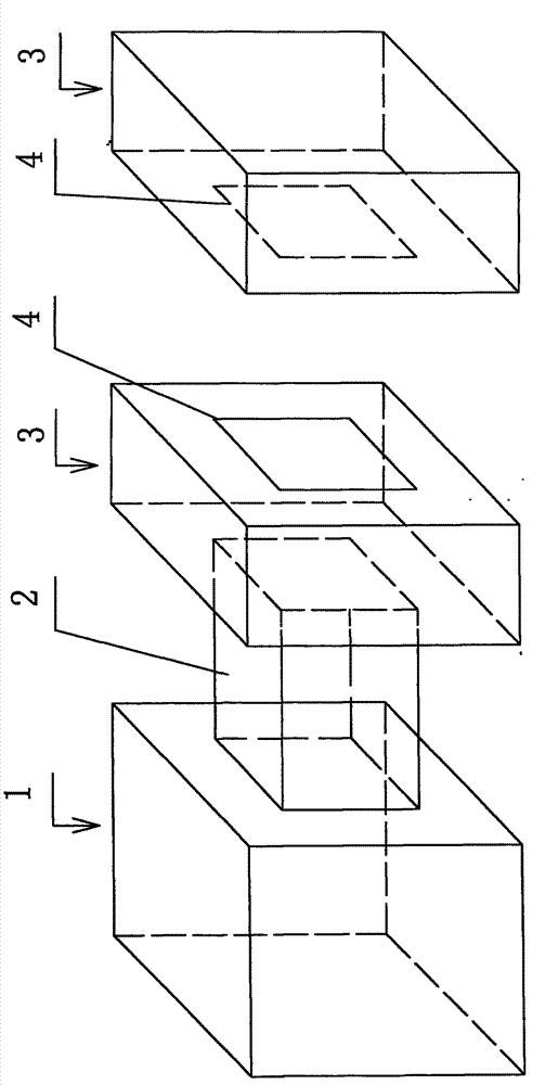
[0015] see figure 2 , figure 2 It is a structural schematic diagram of an electrode network potential test electrolyzer involved in the present invention. Depend on figure 2 It can be seen that the preparation method of the potential test electrolytic cell of the present invention includes the following process: the anode end 3 that is put into the anode test piece is divided into two by the middle, and becomes two separate anode ends. The separation of the two separated anode ends is aligned with the position of the channel 2, and the opening size is 20mm×20mm, and a soft rubber plate 4 for sealing is pasted around the opening.
Login to View More PUM
 Abstract
The invention relates to a preparation method of a potential test electrolyte tank, belonging to the technical field of chlor-alkali equipment. The method comprises the following technical processes of: dividing an anode terminal with an anode test piece into two parts from the middle position to form two separated anode terminals, arranging openings at the separation position of the two separated anode terminals, which aligns to a channel, wherein the size of each of the openings is 20*20 mm, and adhering soft rubber plates for sealing at the periphery of the openings. The preparation methodof the potential test electrolyte tank can be suitable for inspecting a finished product in the production process.
Description
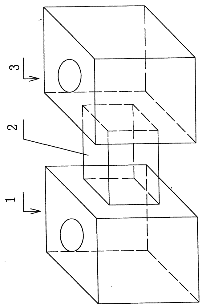
(1) Technical field [0001] The invention relates to an electrolytic cell, in particular to a preparation method of a potential test electrolytic cell. It belongs to the technical field of chlor-alkali equipment. (2) Background technology [0002] The chemical industry standard HG / T3679-2000 stipulates the instruments, equipment, reagents, test pieces, test conditions and test procedures of the electrode network potential test. Its electrolytic cell is an H-shaped transparent cell, and its structural shape should conform to figure 1 As shown, the channel is added with a filter, and the distance between cathode and anode is 160mm±10mm. The cathode end is inserted into the nickel plate used as the electrode, and the anode end is put into the test piece to be tested, with a size of 20mm×20mm. [0003] The electrolytic cell is only suitable for the detection of samples, not for the detection of finished products in the production process. To test products, a small sample must ...
Claims
Login to View More Application Information
Patent Timeline
 Patent Type & Authority Patents(China)
IPC IPC(8): G01N27/28
Inventor 刘跃生
Owner 宏泽(江苏)科技股份有限公司