Flaw detector for wire rope

A flaw detection device and steel wire rope technology, which is applied in the direction of material magnetic variables, etc., can solve the problem that steel wire rope flaw detection takes a lot of time

Active Publication Date: 2010-09-22
HITACHI BUILDING SYST CO LTD
View PDF6 Cites 19 Cited by
  • Summary
  • Abstract
  • Description
  • Claims
  • Application Information

AI Technical Summary

Problems solved by technology

Therefore, since the installation position of the magnetic sensor is also changed in this case, it is necessary to stop the flaw detection measurement of the wire rope and reset the flaw detection device, and there is a problem that the flaw detection measurement of the wire rope takes a lot of time.

Method used


Image

  • Flaw detector for wire rope
  • Flaw detector for wire rope
  • Flaw detector for wire rope

Examples


no. 1 approach

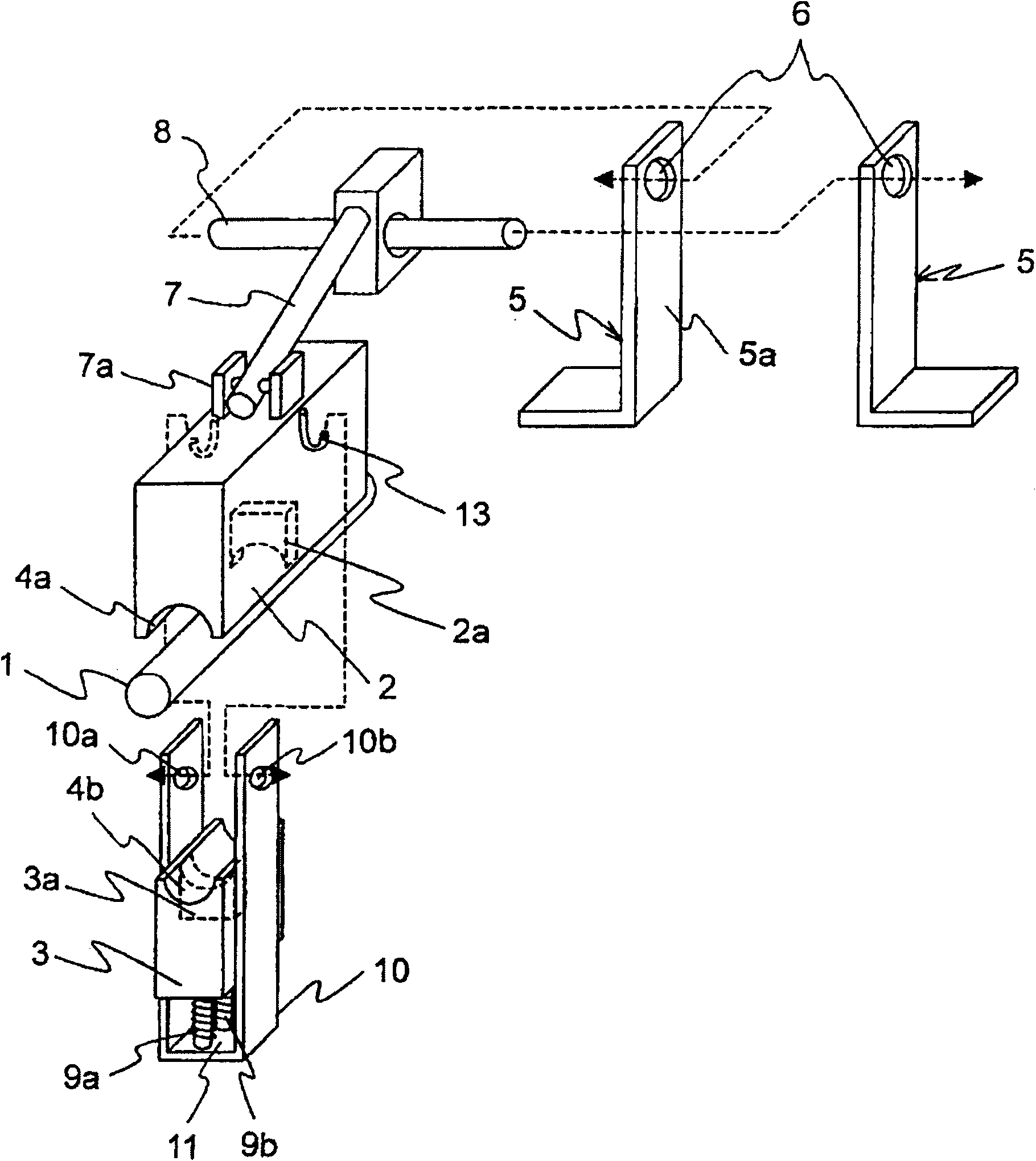
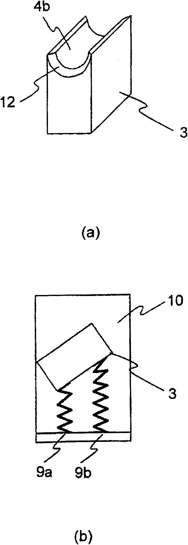
[0034] figure 1 It is an exploded perspective view showing the structure of the first embodiment of the flaw detection device for a steel wire rope according to the present invention. figure 2 is enlarged figure 1 Figure (a) is a perspective view showing the shape of the sensor base with the elastic body on the lower surface, and figure (b) shows the installation of the sensor base with the elastic body on the installation base. A side view of the state of the seat.

[0035] like figure 1 As shown, the first embodiment of the flaw detection device of the steel wire rope of the present invention is suitable for a machine such as an elevator with a steel wire rope 1, and is equipped with: a magnetization mechanism (not shown) that magnetizes the steel wire rope 1 along the length direction; The portion of the wire rope 1 magnetized by the magnetization mechanism includes sensor bases 2 and 3 of the magnetic sensors 2 a and 3 a that detect leakage magnetic flux leaked from a ...

Embodiment approach

[0052] In addition, in the first embodiment of the present invention, the rotating rods 8 are respectively inserted into the through holes 6a of the jig 5 mounted on the external non-working part, and the sensor base 2 as a whole can rotate around the position of the rotating rod 8 with respect to the jig 5 . Since the axis rotates, when a strong impact is received by the above-mentioned strands, the entire sensor base 2 rotates relative to the jig 5 . Therefore, the device can be prevented from malfunctioning due to the impact, and the durability of the device can be improved.

[0053] In addition, in the first embodiment of the present invention, the above-mentioned strands smoothly enter the guide of the sensor base 3 by utilizing the notch portion 12 formed on the side where the wire rope 1 enters in both ends of the guide surface 4b of the sensor base 3. Therefore, the impact generated when the above-mentioned strands enter the sensor base 3 can be reduced, and the load a...

no. 2 approach

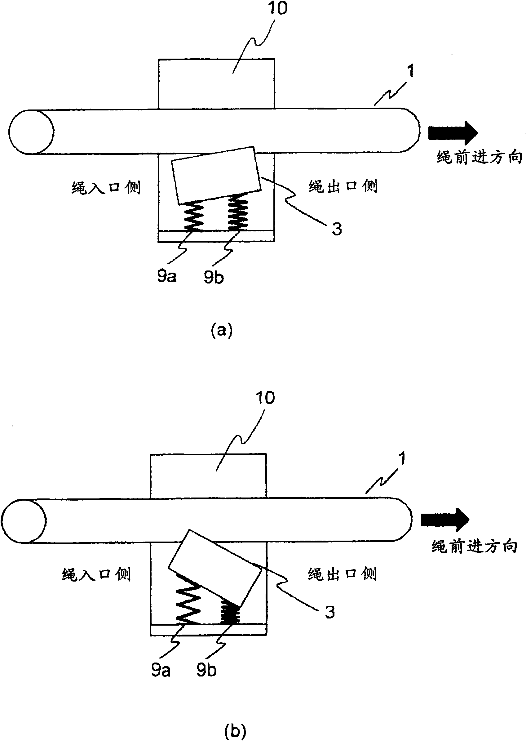
[0056] Figure 4 It is a side view showing the state where the sensor base having an elastic body included in the second embodiment of the flaw detection device for a steel wire rope according to the present invention is mounted on the mounting base.

[0057] like Figure 4 As shown, the difference between the second embodiment of the present invention and the first embodiment of the present invention is that the outlet side of the steel wire rope 1 of the sensor base 3 at both ends of the guide surface 4b is rotatably formed by an elastic body such as a spring 9c , the other structures are the same as those of the first embodiment.

[0058] According to the second embodiment of the present invention constituted in this way, the same effects as those of the above-mentioned first embodiment of the present invention can be obtained. In addition, since the spring 9c is located at both ends of the guide surface 4b of the sensor base 3, the wire rope 1 Therefore, during the above...


PUM


Abstract

The present invention provides a flow detector for a wire rope, which can moderate the effect of the force generated by the deformation contained in the wire rope or the strand exposed out from the wire rope. The flaw detector for wire rope comprises the following components: a magnetizing mechanism which magnetizes the wire rope (1); two sensor bases (2, 3) which are configured to cover the circumferential direction of the part of wire rope (1) magnetized by the magnetizing mechanism and respectively contain magnetic sensors (2a, 3a) that detect the leakage flux leaked from the damaged part generated by the part of the wire rope (1). The sensor bases (2, 3) is rotatably equipped relatively to the moving in the length direction of the wire rope (1), wherein the sensor base (3) is rotatably provided through two elastomers (9a, 9b), and is pushed and pressed and kept on the wire rope (1) through the elastomers (9a, 9b).

Description

technical field [0001] The invention relates to a flaw detection device for a steel wire rope using an electromagnetic flaw detection method. Background technique [0002] Steel wire ropes are mostly used in elevators, elevators, cable cars, cranes, etc. However, depending on the frequency of use, local damage due to fatigue or wear occurs, and the strands of the constituent elements are sequentially broken. The number of such breakages increases with time, and when the number of breakages exceeds a predetermined value, it is judged that the life of the unused wire rope has reached the end of life, and the wire rope is replaced. Therefore, it is necessary to evaluate whether the steel wire rope can be used safely by measuring the number of broken strands by periodic inspection. [0003] In order to check the number of breakages of the strands of such a steel wire rope in use, an electromagnetic flaw detection method is known as a flaw detection method of a steel wire rope t...

Claims


Application Information

Patent Timeline
Patent Type & Authority Applications(China)
IPC IPC(8): G01N27/83
Inventor 浅井大辅五十岚芳治松本俊昭大西友治
Owner HITACHI BUILDING SYST CO LTD
Why Eureka
Try Eureka