Holographic image display systems

A hologram, holographic technology, applied in the direction of hologram optical elements, characteristics of hologram objects, properties/properties of holograms, etc.

Inactive Publication Date: 2010-09-22
LIGHT BLUE OPTICS
View PDF8 Cites 21 Cited by
  • Summary
  • Abstract
  • Description
  • Claims
  • Application Information

AI Technical Summary

Problems solved by technology

However, for spatial filtering to be practiced, it is desirable that there be some spatial separation in the playback field between the displayed image and the portion of the playback field to be attenuated

Method used


Image

  • Holographic image display systems
  • Holographic image display systems
  • Holographic image display systems

Examples


Embodiment Construction

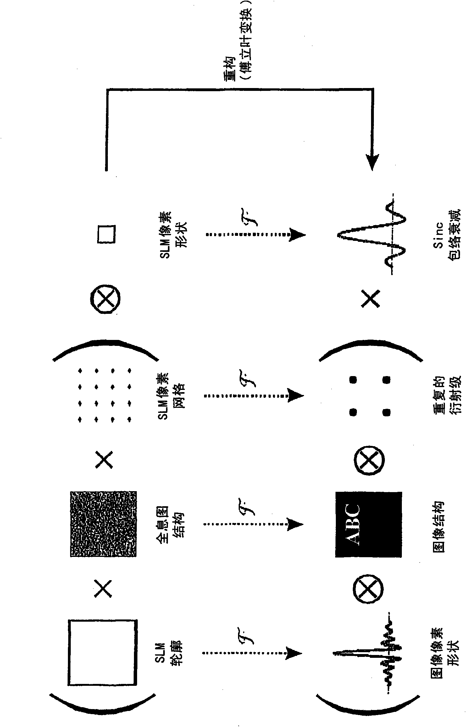
[0036] This invention describes a technique for increasing the diffraction efficiency of holographic projections by shifting the SLM pixel diffraction (sinc decay) envelope.

[0037] Holographically formed images suffer from an effect called "sinc decay" caused by square pixels on the SLM, where the SLM imposes a sinc-shaped intensity modulation centered at the zeroth order across the reconstructed field, resulting in Undesired strength reduction in the edge direction. This leads to two problems.

[0038] 1. Image intensity is no longer uniform across the field. This can be compensated by pre-multiplying the input image by modulating the inverse of the sinc envelope.

[0039] 2. The point gradually decays along the direction away from the center of the sinc envelope, resulting in a significant decrease in diffraction efficiency. Precisely, light moves from the edge of the first diffraction order (first sinc lobe) to an undesired higher diffraction order (sinc tail). So to ...


PUM


Abstract

This invention relates to methods and apparatus for displaying images holographically. A method of displaying an image holographically using a spatial lightmodulator (SLM), said SLM having a plurality of SLM pixels, the method comprising: displaying a diffraction pattern on said pixels of said SLM; and illuminating said pixels of said SLM such that light diffracted by said diffraction pattern on said SLM pixels comprises a content of said displayed image, a variation in brightness of said displayed image across said displayed image being modulated by an intensity envelope determined by the diffraction pattern of an individual said pixel, for example a sinc envelope; and wherein the method further comprises moving a peak or centre of gravity of said intensityenvelope away from a zero order spot and towards a centre of said displayed image by imposing a pattern of phase delay across said SLM pixels, said pattern of phase delay repeating at a spatial interval corresponding to a pixel interval of said SLM.

Description

technical field [0001] The present invention relates to methods and devices for holographically displaying images. Background technique [0002] Techniques for displaying images holographically have been described previously (see, e.g., WO2005 / 059660, WO2006 / 134398, WO2006 / 134404, WO2007 / 031797, WO2007 / 085874, WO2007 / 110688, the entire contents of which are hereby incorporated by reference ). These techniques have a wide variety of applications including, for example, in hand-held battery-operated devices such as digital cameras, mobile phones, portable media players, laptop computers, and the like. In these and other applications, however, there is often a need to increase operating efficiency. [0003] The prior art can be found in EP1702243A; EP1498766; and in "Holographic projection of arbitrary light patterns with a suppressed zero-order beam" by Palima D. and Daria V.R., 2007, Vol46, No20, Applied Optics. [0004] The present invention will describe techniques that ...

Claims


Application Information

Patent Timeline
Patent Type & Authority Applications(China)
IPC IPC(8): G03H1/22G02F1/1335G02F1/1343
CPCG03H2240/41G03H2240/61G03H2225/55G02F1/133553H04N9/3173G03H2225/32G02F1/134309G03H2223/13H04N9/3161G03H1/2294H04N9/3197G03H2223/19G03H2210/441G03H2240/42G03H2001/0825G02F2201/128G03H1/02G03H2001/0224G03H2223/18G03H1/22H04N5/7416G02B30/00
Inventor 阿德里安·詹姆斯·卡贝尔保罗·劳特利
Owner LIGHT BLUE OPTICS
Why Eureka
Try Eureka