
Optical displacement detection device and operation method thereof

A detection device and displacement technology, applied in the direction of instrument, electrical digital data processing, data processing input/output process, etc., can solve problems such as malfunction, cursor jitter, cursor automatic drift, etc., and achieve the effect of eliminating malfunction.

Inactive Publication Date: 2010-10-06
PIXART IMAGING INC
View PDF3 Cites 12 Cited by
  • Summary
  • Abstract
  • Description
  • Claims
  • Application Information

AI Technical Summary

Problems solved by technology

However, when using this kind of optical motion detection device, even if the user's finger does not touch the motion detection device, the motion detection device is still susceptible to interference from external artificial light sources to cause malfunctions, for example, when the motion detection device is stationary , the cursor will still shake due to the interference of external artificial light sources; or when the motion detection device is moved, it will output a displacement signal by itself, causing the cursor to automatically drift, etc.

Method used


Image

  • Optical displacement detection device and operation method thereof
  • Optical displacement detection device and operation method thereof
  • Optical displacement detection device and operation method thereof

Examples


Embodiment Construction

[0025] In order to make the above and other objects, features and advantages of the present invention more apparent, a detailed description will be given below with reference to the accompanying drawings.

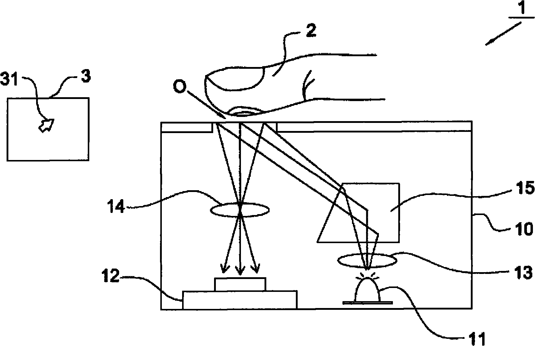
[0026] Please refer to figure 1 As shown, it shows an optical displacement detection device 1 according to an embodiment of the present invention. The optical displacement detection device 1 is used for sensing the position change of the object 2 to relatively control the operation of the image display 3 , such as controlling the movement of the cursor 31 on the image display 3 or the operation of software installed in the image display 3 . In this embodiment, although the object 2 is shown as a finger, it is not used to limit the present invention, and the object 2 can also be a round stick, a pen or other suitable objects. For example, when the object 2 is a finger, the optical displacement detection device 1 detects the change of the fingerprint image on the finger to d...


PUM


Abstract

The invention relates to an operation method of an optical displacement detection device. The method comprises the following steps of: capturing a plurality of images; obtaining a displacement amount according to the plurality of images; obtaining characteristic value changes of the plurality of images; and suppressively outputting the displacement amount when the characteristic value changes accord with preset rules. The invention also provides an optical displacement detection device.

Description

technical field [0001] The invention relates to an optical displacement detection device and its operating method, in particular to an optical displacement detection device capable of eliminating interference from external artificial light sources and its operating method. Background technique [0002] The cursor displayed on the screen in the early days is controlled by a mechanical displacement detection device, such as a wheel mouse. The mechanical displacement detection device has a rolling ball inside and is usually placed on a specific surface, such as The surface of the mouse pad that is manipulated by the user. However, the mechanical displacement detection device is limited in use because it cannot be applied to any surface; in addition, after a period of use, with the deterioration of the mechanical structure and the accumulation of dust, it is prone to malfunction or uncontrollable situation. Therefore, an optical displacement detection device, such as an optica...

Claims


Application Information

Patent Timeline
Patent Type & Authority Applications(China)
IPC IPC(8): G06F3/033G06F3/042G06F3/0354
Inventor 陈信嘉苏宗敏赵子毅
Owner PIXART IMAGING INC
Learn More