

Combined convection/effusion cooled one-piece can combustor
A technology of combustor and combustion section, which is applied in the direction of cooling of turbine/propulsion device, combustion chamber, combustion method, etc., and can solve problems such as unaffordable
Inactive Publication Date: 2010-10-13
GENERAL ELECTRIC CO
View PDF6 Cites 2 Cited by
- Summary
- Abstract
- Description
- Claims
- Application Information
AI Technical Summary
Problems solved by technology
However, the combustion gases originate in the combustion chamber before entering the turbine inlet, and the combustion chamber reaches operating temperatures well above 1500°F, and even the most advanced alloys cannot withstand prolonged use at these temperatures
Method used
View moreImage
Smart ImageViewing Examples

Examples
Embodiment Construction
Login to View More PUM
 Abstract
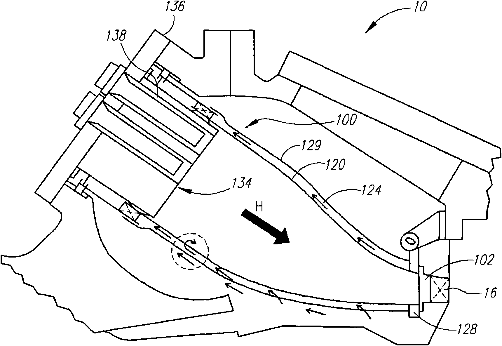
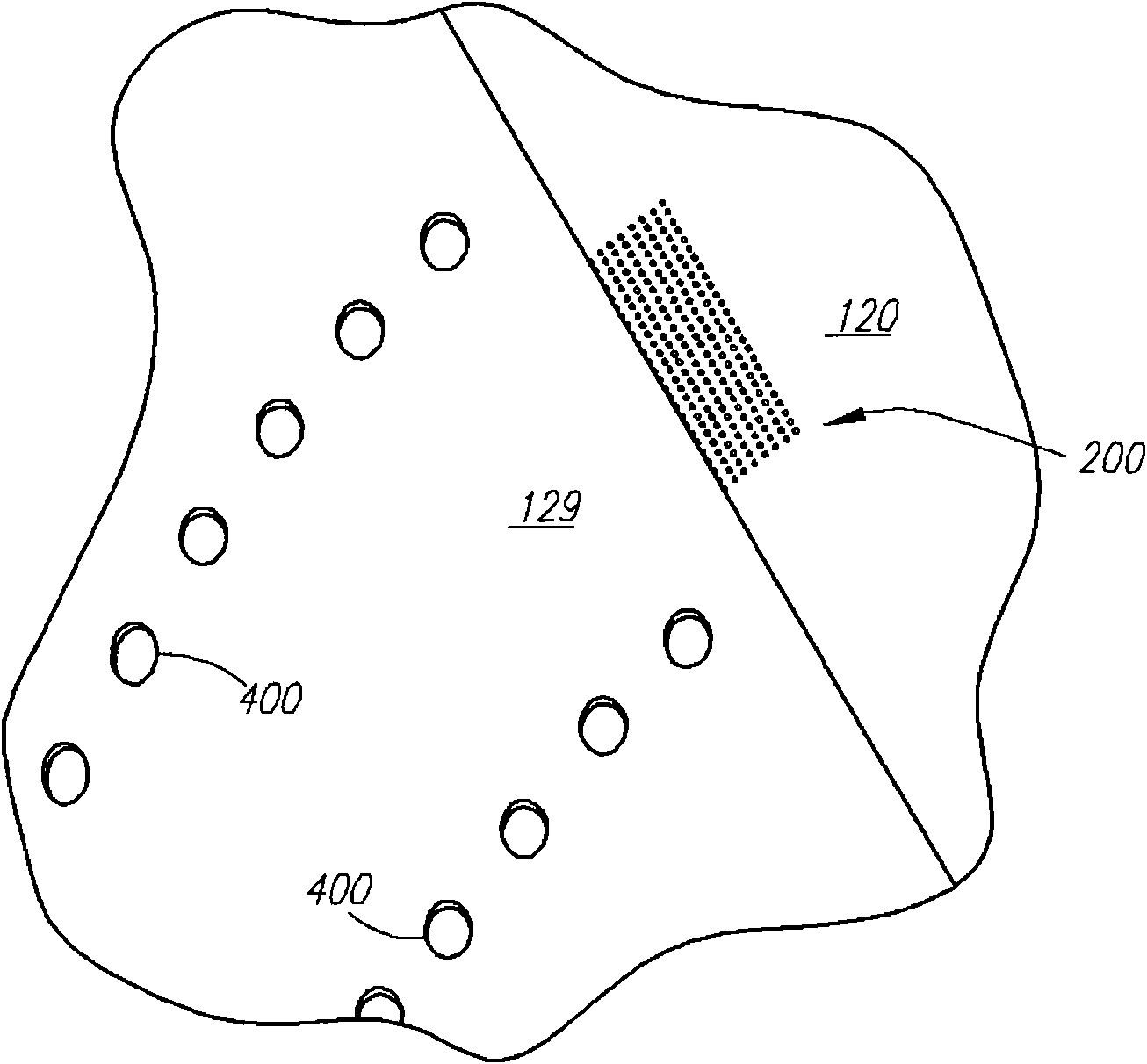
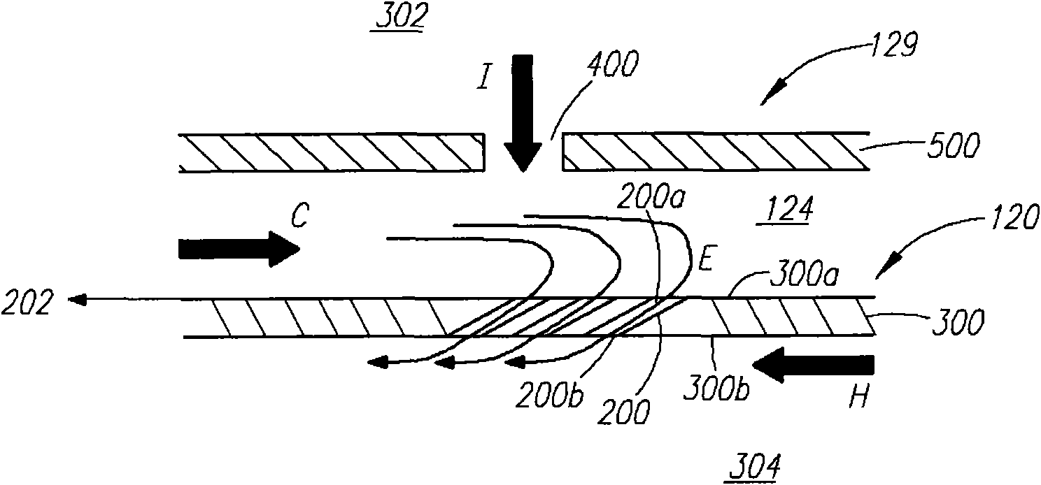
The invention relates to a combined convection / effusion cooled one-piece can combustor. An industrial turbine engine comprises a combustion section, an air discharge section downstream of the combustion section, a transition region between the combustion and air discharge section, a combustion transition piece (120) and a sleeve (129). The transition piece (120) defines an interior space (304) for combusted gas flow. The sleeve (129) surrounds the combustor transition piece (120) so as to form a flow annulus (124) between the sleeve (129) and the transition piece (120). The sleeve (129) includes a first set of apertures (400) for directing cooling air (I) from compressor discharge air into the flow annulus (124). The transition piece (120) includes an outer surface (300a) bounding the flow annulus (124) and an inner surface (300b) bounding the interior surface (304), and includes a second set of apertures (200) for directing cooling air in the flow annulus (124) to the interior space (304). Each of the second set of apertures (200) extends from an entry portion (200a) on the outer surface (300a) to an exit portion (200b) on the inner surface (300b).
Description
technical field [0001] The present invention relates generally to means for cooling gas turbine components, and more particularly to cooling a one-piece can combustor by a combination of convective cooling and effusion cooling. Background technique [0002] Gas turbines can operate with higher efficiency if the turbine inlet temperature can be raised to a maximum. However, the combustion gases originate in the combustion chamber before entering the turbine inlet, and the combustion chamber reaches operating temperatures well above 1500°F, and even the most advanced alloys cannot withstand prolonged use at these temperatures. Thus, the performance and life of the turbine is greatly dependent on the degree of cooling available to the turbine components exposed to extreme thermal conditions. [0003] The general concept of using compressor discharge air to cool turbine components is known in the art. However, developments and changes in turbine design have not necessarily bee...
Claims
Login to View More Application Information
Patent Timeline
 Patent Type & AuthorityApplications(China)
IPC IPC(8): F02C7/18
CPCF23R3/06F23R2900/03041F23R3/005
InventorR·J·基拉K·W·麦马汉
OwnerGENERAL ELECTRIC CO