Feeding machine and feeding uniformity testing method

A feeding machine and feed technology, which is applied in the testing, measuring devices, instruments, etc. of machine/structural components, can solve the problems of inaccurate test and troublesome feed collection, etc. Simple, easy-to-use effects

Active Publication Date: 2013-03-27
ZHEJIANG FORDY MACHINERY
View PDF2 Cites 0 Cited by
  • Summary
  • Abstract
  • Description
  • Claims
  • Application Information

AI Technical Summary

Problems solved by technology

In order to formulate specific indicators of uniformity, I tried to use the method of drawing lines on the field, that is, draw the same size and equidistant boxes on the field, and compare the feed in the box after the feeding test to calculate the error, but the feed will rebound when it hits the ground. , the feed in the box is not necessarily the feed at the landing point, so the test is not very accurate, and the collection of feed on the ground is also troublesome

Method used


Image

  • Feeding machine and feeding uniformity testing method
  • Feeding machine and feeding uniformity testing method
  • Feeding machine and feeding uniformity testing method

Examples


Embodiment Construction

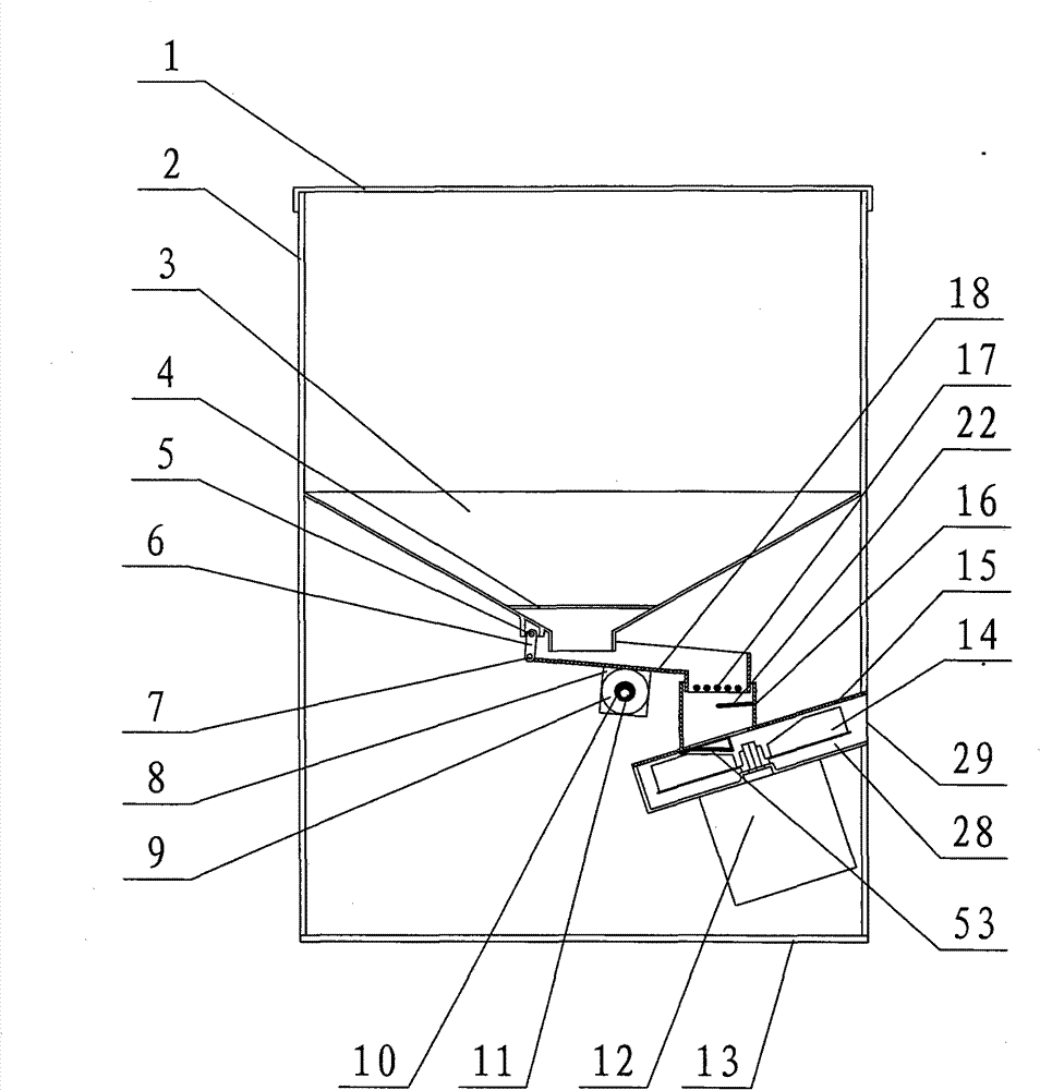
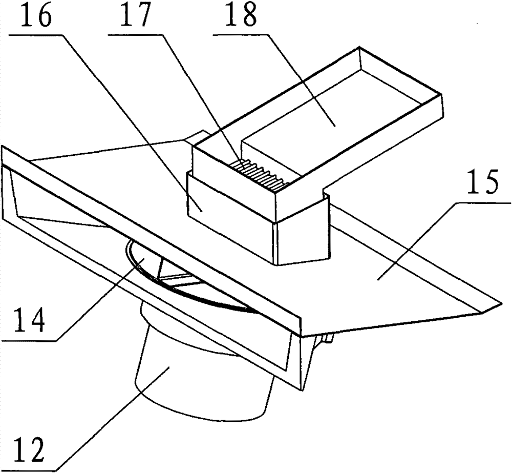
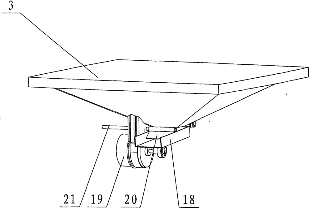
[0038] The present invention will be further described below with specific embodiment, see Figure 1-13 :

[0039] A feeding machine of the present invention is mainly composed of a cabinet 2, a controller 34, a feeding mechanism, a throwing mechanism, a hopper 3, a case cover 1, etc., and the throwing mechanism is mainly composed of a throwing chamber 28, a throwing motor 12, The throwing tray top plate 15, the throwing tray 14, etc., the throwing mechanism is installed obliquely on the lower part of the cabinet 2, the throwing port 29 is higher than the inside, and a feeding tray 53 is formed under the throwing tray top plate 15, and the feeding tray The three sides of 53 are connected to the top plate 15 of the throwing tray, and one side is opened as a feeding port. The feed sent by the feeding mechanism falls from the open side of the feeding tray 53 to the throwing tray 14 in rows, and the opposite position of the throwing tray 14 is It is fixed, and after adjusting the...


PUM


Abstract

The invention relates to a feeder, which mainly consists of a box, a controller, a baiting mechanism, an extractor mechanism, a material hopper, a box cover and the like. The box consists of four plastic boards and is provided with a fixing window. One side of the fixing window is provided with a platform provided with the controller. The platform is provided with two small windows the lower parts of which are respectively connected with a shaft fixedly. One end of the supporting piece of the box cover is fixed at one side of the box cover and the other end thereof extends into the lower part of the small window and is movably connected with the shaft. The other side of the fixing window is provided with a magnetic chamber the upper part of which is provided with a small groove and the lower part of which is provided with a check block. Iron pieces and a magnetic steel are arranged in the magnetic chamber. The two sides of the magnetic steel are respectively provided with one iron piece. The iron piece is punched into a step shaft, the middle part protrudes and extends out of the small groove and the lower part is blocked by the check block. The two iron pieces can be blocked in the magnetic chamber by adding the magnetic steel between the two iron pieces. The other side of the box cover is embedded with an iron board. The position of the iron board corresponds to the magnetic chamber. The magnetized iron pieces attract the iron board embedded on the box cover so that the box cover is closed.

Description

technical field [0001] The invention relates to a feeding machine, in particular to a feeding machine for aquaculture, belonging to aquaculture machinery. Background technique [0002] Feeding machine is an indispensable equipment for aquaculture. Usually, the feeding mechanism of the feeding machine includes mechanical vibration type, electromagnetic vibration type, stirring cage feeding type, etc. The electromagnetic vibration type is easy to cause fatigue fracture of the vibrating plate or elastic body, and the stirring cage feeding feeding type has a high feed breaking rate, and is currently the most commonly used. The most is the mechanical vibration type. The existing mechanical vibration type drop mechanism is driven by the motor and the eccentric wheel. The connecting rod makes the feeding box swing around the hinge axis point. The hinges swing around the pivot point. This kind of falling mechanism can only make the feed slide down when the feeding box has a certain...

Claims


Application Information

Patent Timeline
Patent Type & Authority Patents(China)
IPC IPC(8): A01K61/02G01M99/00
Inventor 吴海钧
Owner ZHEJIANG FORDY MACHINERY
Why Eureka
Try Eureka