Feeding machine

A feeding machine and chassis technology, applied in fish farming, application, animal husbandry, etc., can solve the problems of vibrating plate or elastic body fatigue fracture, failure to achieve control effect, troublesome operators, etc., to achieve low cost, prevent Stealing feed and biting wires, the effect of simple structure

Active Publication Date: 2010-06-30
ZHEJIANG FORDY MACHINERY
View PDF2 Cites 14 Cited by
  • Summary
  • Abstract
  • Description
  • Claims
  • Application Information

AI Technical Summary

Problems solved by technology

Usually, the feeding mechanism of the feeding machine includes mechanical vibration type, electromagnetic vibration type, stirring cage feeding type, etc. The electromagnetic vibration type is easy to cause fatigue fracture of the vibrating plate or elastic body, and the stirring cage feeding feeding type has a high feed breaking rate, and is currently the most commonly used. The most is the mechanical vibration type. The existing mechanical vibration type drop mechanism is driven by the motor and the eccentric wheel. The connecting rod makes the feeding box swing around the hinge axis point. The hinges swing around the pivot point. This kind of falling mechanism can only make the feed slide down when the feeding box has a certain slope. If you want to increase the feeding speed, you must increase the slope of the feeding box. If the slope is too large, feed It will slide down automatically, and the control effect cannot be achieved, so the patented design of the angle adjustment mechanism will cause trouble to the operator

Method used


Image

  • Feeding machine
  • Feeding machine
  • Feeding machine

Examples


Embodiment Construction

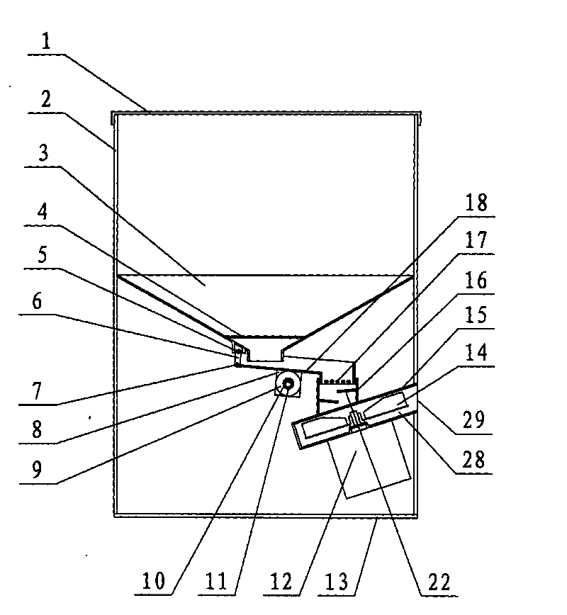
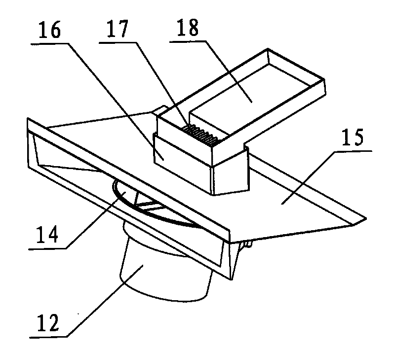
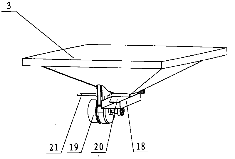
[0030] The present invention will be further described below with specific embodiment, see Figure 1-9 :

[0031] A feeding machine of the present invention is mainly composed of a casing 2, a control box 34, a feeding mechanism for throwing movement, a throwing motor 12, a throwing tray 14, a box cover 1, a box bottom plate 13, etc., the so-called throwing movement The feeding mechanism is: there is a lower shaft 7 at the non-feeding port end of the feeding chute 18, the lower shaft 7 is connected to the upper shaft 5 through the connecting rod 6, the upper shaft 5 is fixed under the hopper 3, and there is a bearing seat 8 under the feeding chute 18 , the bearing seat is divided into two halves, one half of which is integrated with the feeding trough, and there is a ball bearing 9 in the bearing seat 8, the ball bearing 9 is connected to the motor shaft 11 through the eccentric sleeve 10, and the motor shaft 11 supports the middle part of the feeding chute 18, the so-called ...


PUM


Abstract

The invention provides a feeding machine, which mainly consists of a machine box, a controller, a baiting mechanism which carries out throwing movement, a material throwing motor, a material throwing disc, a box cover, a box bottom plate and the like, wherein a lower shaft is arranged at the baiting opening end of a material passing groove, the lower shaft is connected with an upper shaft through a connecting rod, the upper shaft is fixed under a material hopper, a bearing seat is arranged under the material passing groove, a roller bearing is arranged in the bearing seat and is connected with a motor shaft through an eccentric sleeve, and the motor shaft is supported on the middle of the material passing groove. The throwing movement refers to the movement that when the baiting motor rotates in the positive direction, the eccentric sleeve drives the roller bearing to revolute around the motor shaft, at the same time, the autorotation of the roller bearing drives the material passing groove to do the circumferential reciprocating movement, and an upper shaft and a lower shaft of the non-baiting end are hinged with the connecting rod for swinging, so the feedstuff is gradually thrown towards the baiting opening in the material passing groove to enter a material collector and to fall on the material throwing disc.

Description

technical field [0001] The invention relates to a feeding machine, in particular to a feeding machine for aquaculture, belonging to aquaculture machinery. Background technique [0002] Feeding machine is an indispensable equipment for aquaculture. Usually, the feeding mechanism of the feeding machine includes mechanical vibration type, electromagnetic vibration type, stirring cage feeding type, etc. The electromagnetic vibration type is easy to cause fatigue fracture of the vibrating plate or elastic body, and the stirring cage feeding feeding type has a high feed breaking rate, and is currently the most commonly used. The most is the mechanical vibration type. The existing mechanical vibration type drop mechanism is driven by the motor and the eccentric wheel. The connecting rod makes the feeding box swing around the hinge axis point. The hinges swing around the pivot point. This kind of falling mechanism can only make the feed slide down when the feeding box has a certain...

Claims


Application Information

Patent Timeline
Patent Type & Authority Applications(China)
IPC IPC(8): A01K61/02
Inventor 吴海钧
Owner ZHEJIANG FORDY MACHINERY
Why Eureka
Try Eureka