Supercharge Your Innovation With Domain-Expert AI Agents!

Vehicle skid control device

A slip control and slip technology, which is applied to electrical devices, vehicle components, brakes, etc., can solve problems such as resolver instability and rising angular acceleration of detection signals, and achieve the effect of avoiding misjudgment of slip

Active Publication Date: 2013-09-04
TOYOTA JIDOSHA KK
View PDF1 Cites 0 Cited by
  • Summary
  • Abstract
  • Description
  • Claims
  • Application Information

AI Technical Summary

Problems solved by technology

[0004] However, in a vehicle in which the drive shaft is driven by the drive torque output from the electric motor, when the rotational speed of the electric motor reaches a high rotational speed range, PWM (Pulse Wide Modulation: Pulse Width Modulation) of an inverter for supplying AC power to the electric motor may be controlled. ) signal and the pick-up period of the resolver (resolver), which detects the rotor position (angular velocity) of the motor, resonates periodically, and instability occurs in the resolver detection signal
Such instability of the resolver detection signal may be mistakenly judged to mean that the angular acceleration of the motor is increased (slip occurs), and it is irrelevant to the slipping running, and it may cause an unexpected malfunction that limits the driving torque. reason

Method used


Image

  • Vehicle skid control device
  • Vehicle skid control device

Examples


Embodiment Construction

[0014] Hereinafter, embodiments of the present invention will be described with reference to the drawings.

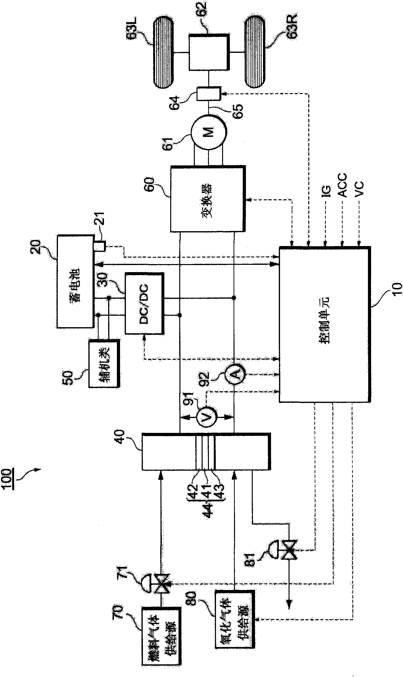
[0015] figure 1 A system configuration of a fuel cell system 100 functioning as an onboard power supply system of a fuel cell vehicle is shown.

[0016] The fuel cell stack 40 is a solid polymer electrolyte type single cell stack in which a plurality of single cells are stacked in series. The fuel cell stack 40 includes a membrane-electrode assembly (MEA) 44 formed by forming an anode 42 and a cathode 43 on both surfaces of a polymer electrolyte membrane 41 by screen printing or the like. The electrolyte membrane 41 is composed of a proton-conductive particle exchange membrane or the like formed of a fluororesin or the like. Both sides of the membrane-electrode assembly 44 are sandwiched by ribbed separators (not shown), and groove-shaped anode gas passages and cathode gas passages are formed between the separators, the anode 42 and the cathode 43 , respectively. In ...


PUM


Abstract

Provided is a vehicle skid control device that avoids a skid erroneous judgment in a high revolution range of a motor. The vehicle skid control device detects the number of revolutions of the motor. When the number of revolutions of the motor is equal to or larger than a predetermined threshold value Nm, the vehicle skid control device prohibits a skid judgment. When the number of revolutions of the motor is smaller than the predetermined threshold value Nm, the vehicle skid control device permits the skid judgment. When the number of revolutions of the motor is equal to or larger than the threshold value Nm, the skid judgment is prohibited. Accordingly, it is possible to avoid the skid erroneous judgment in the high revolution range with the number of revolutions equal to or larger than Nm.

Description

technical field [0001] The present invention relates to a slip control device for controlling an electric motor that transmits power to a drive shaft connected to a drive wheel of a wheel. Background technique [0002] Generally, when the vehicle is running, the drive wheels may slip during rapid acceleration, driving on low-friction road surfaces, etc. Such slippage of the drive wheels impairs the safety of vehicle running, and therefore, development of traction control that determines the slippage of the drive wheels and limits the drive torque is being developed. For example, Japanese Patent Application Laid-Open No. 2004-112973 mentions traction control in which it is determined that slip has occurred when the angular acceleration of a drive shaft that transmits power to drive wheels exceeds a predetermined threshold, and the drive torque is limited. This publication also mentions that even when the angular acceleration of the drive shaft exceeds a predetermined thresho...

Claims


Application Information

Patent Timeline
Patent Type & Authority Patents(China)
IPC IPC(8): B60L9/18B60L11/18
CPCB60T8/48B60T8/175B60L3/10
Inventor 吉田道雄马屋原健司西田知之
Owner TOYOTA JIDOSHA KK
Features
  • R&D
  • Intellectual Property
  • Life Sciences
  • Materials
  • Tech Scout
  • Unparalleled Data Quality
  • Higher Quality Content
  • 60% Fewer Hallucinations
Learn More