Air flow-producing device, such as a vacuum cleaner or a blower

a technology of air flow and vacuum cleaner, which is applied in the direction of cleaning filter means, electric apparatus casings/cabinets/drawers, cell components, etc., can solve the problems of damage to the components of the vacuum cleaner, existing vacuum cleaners or blowers and their individual components are not suited for outdoor use, and the vacuum cleaner is not suitable for heavy-duty use. , to achieve the effect of reducing heat, reducing charge time and increasing the cycle life of the battery

Active Publication Date: 2010-05-11
MILWAUKEE ELECTRIC TOOL CORP
View PDF224 Cites 936 Cited by
  • Summary
  • Abstract
  • Description
  • Claims
  • Application Information

AI Technical Summary

Benefits of technology

[0022]Further, in some aspects, the invention generally provides a multiple-port battery charger including a separate and dedicated charging circuit for each charging port. This configuration allows the remaining charging circuits to be operable if one charging circuit should fail.
[0023]In some aspects of the invention, the heavy-duty construction of the electrical component allows the electrical component and its sub-components to withstand impacts after falling several feet or being impacted by other objects, in addition to protecting an attached battery from jarring loose as a result of the impact.
[0024]In some aspects of the invention, the contaminant-resistant air vents prevent any liquid or solid contaminants from entering the housing. Also, a series of drains may be incorporated within the housing to purge any contaminant that may enter the housing, and the charging circuits are suspended and kept out of contact from such contaminants.
[0025]In some aspects of the invention, a battery terminal cover prevents any contaminants from contacting the battery terminals when a battery is not connected with the electrical component. The cover also provides a sweeping action to keep clean the interconnection between the battery terminals and the battery.
[0027]In some aspects of the invention, the temperature rate termination technique of the charging routine reduces charge time by several minutes, reduces heat due to charging, and / or increases the cycle life of the battery.
[0028]In some aspects of the invention, the independent charging circuits provide the user increased reliability such that a failure of one charging circuit does not result in a complete failure of the multiple port battery charger.

Problems solved by technology

Existing vacuum cleaners or blowers and their individual components are not suited for heavy-duty use commonly found at a work site, including impacts from falling objects or from the vacuum cleaner falling or impacting an obstacle.
Also, existing vacuum cleaners and blowers and their individual components are not suited for outdoor use, including being exposed to weather (i.e. sun, rain, wind, etc.) and other contaminants (i.e. dirt, sand, gravel, mud, sawdust, etc.).
Weather and contaminants can damage the components of the vacuum cleaner and may render the vacuum cleaner inoperable.

Method used


Image

  • Air flow-producing device, such as a vacuum cleaner or a blower
  • Air flow-producing device, such as a vacuum cleaner or a blower
  • Air flow-producing device, such as a vacuum cleaner or a blower

Examples


Embodiment Construction

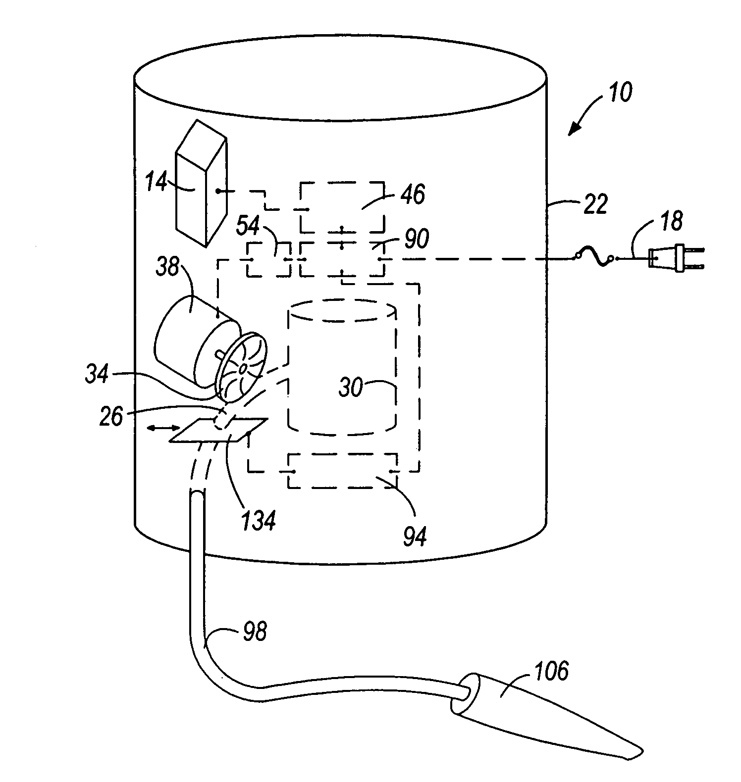
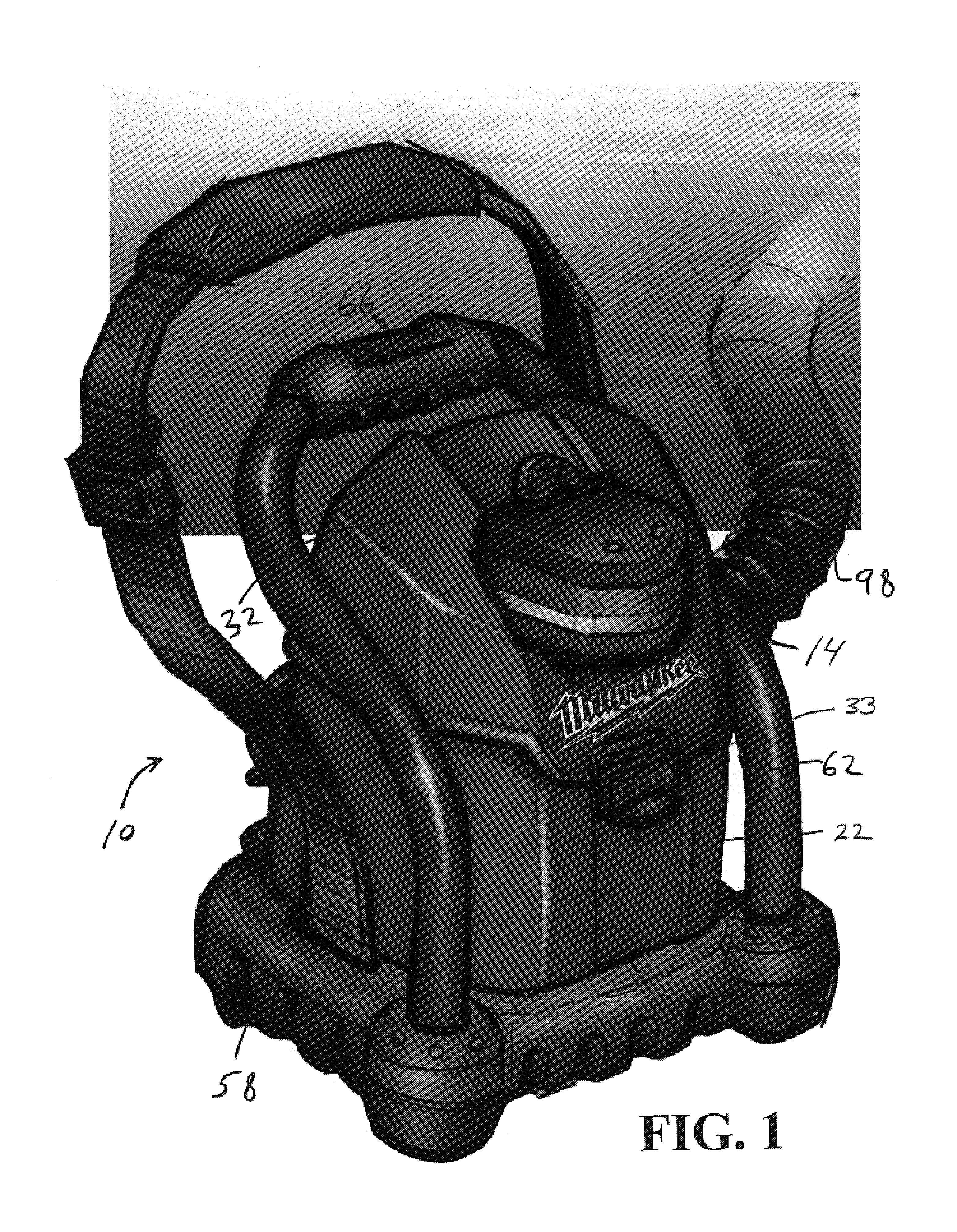
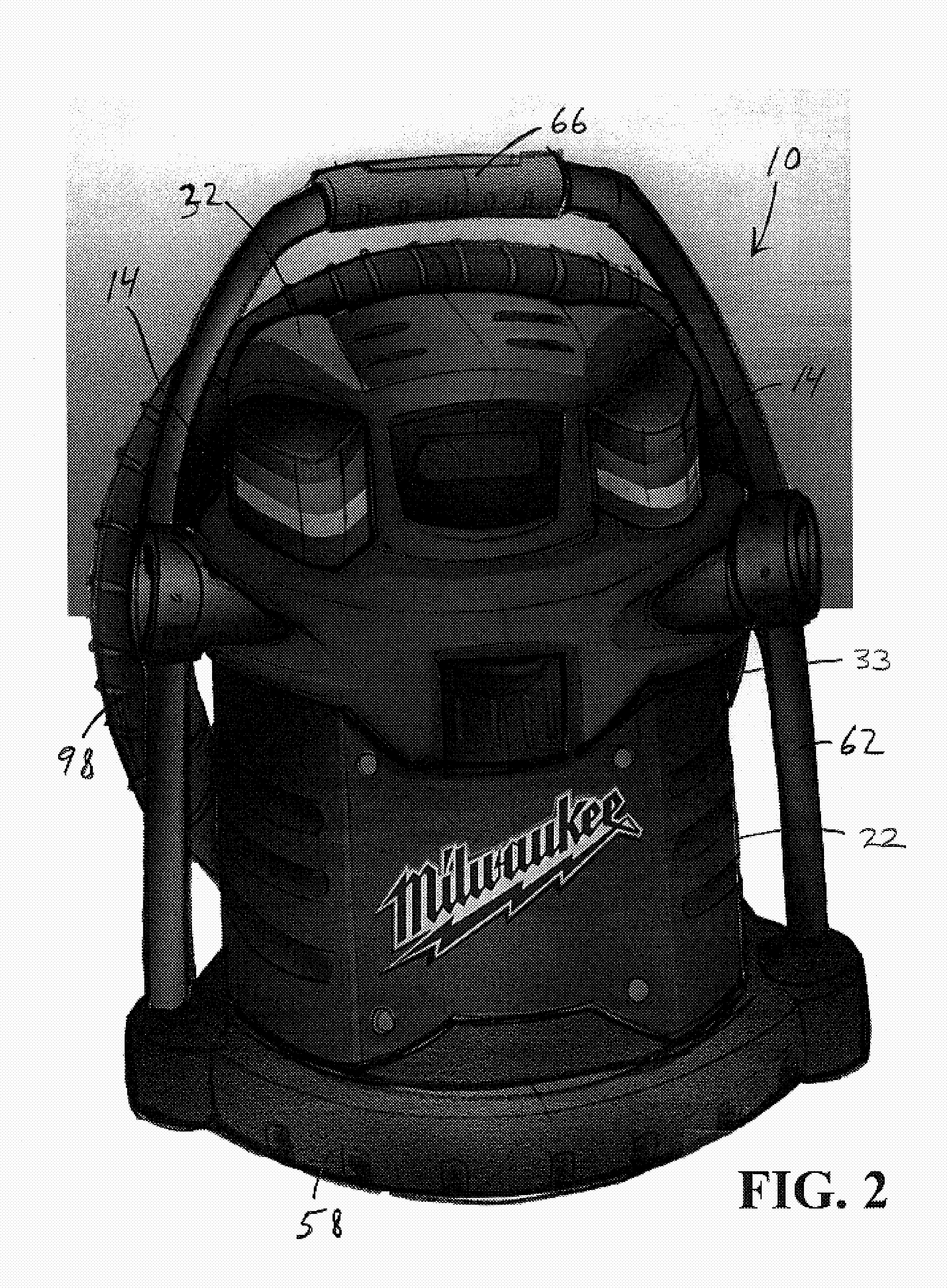
[0072]Constructions of an air flow-producing device, such as, for example, a vacuum cleaner 10, embodying independent aspects of the invention are illustrated in FIGS. 1-35. It should be understood that the independent aspects of the invention disclosed herein may be incorporated in any of the vacuum cleaner constructions illustrated in FIGS. 1-35. As such, the same reference numeral will be used to reference each vacuum cleaner construction illustrated in FIGS. 1-35. It should be understood that, in some aspects, the air flow-producing device may be another air flow-producing device, such as, for example, a blower. It should also be understood that some independent aspects of the invention may be applied to another type of device, such as, for example, a power tool (e.g., hand-held or stationary), audio device, video device, etc.

[0073]In general, in some aspects, the vacuum cleaner 10 is constructed for heavy-duty use in harsh working environments (for electrical equipment) such as...


PUM

PropertyMeasurementUnit
electricalaaaaaaaaaa
poweraaaaaaaaaa
charge levelaaaaaaaaaa

Abstract

Electrical components and vacuums. In some aspects, the invention provides an electrical component including a housing defining a passageway, a motor supported by the housing, the motor being selectively electrically connectable with a power source, a fan connected to the motor and operable to generate an airflow through the passageway, an electrical circuit supported by the housing, the electrical circuit being selectively electrically connectable with the power source, and a power-tool battery electrically connectable with the electrical circuit such that power is selectively transferred between the battery and the electrical circuit, the battery being connectable to the housing. In some aspects, the invention provides a vacuum.

Description

RELATED APPLICATIONS[0001]The present application claims the benefit of co-pending Provisional Application Ser. No. 60 / 578,029, filed Jun. 8, 2004, and co-pending Provisional Application Ser. No. 60 / 490,190, filed Jul. 25, 2003, the entire specifications of both are hereby incorporated by reference.FIELD OF THE INVENTION[0002]This invention relates generally to an air flow-producing device and, more particularly, to vacuum cleaners or blowers.SUMMARY OF THE INVENTION[0003]Typically, an air flow-producing device includes a housing supporting a motor operable to generate an air flow through a passageway. The motor may drive an air flow-generating mechanism, such as a fan.[0004]In a vacuum cleaner, the housing defines a debris chamber to collect and store vacuumed debris therein. The passageway in the housing fluidly connects the debris chamber and the ambient surroundings of the housing. The motor is selectively connectable with a power source to drive the air flow-generating mechanis...

Claims


Application Information

Patent Timeline
Patent Type & Authority Patents(United States)
IPC IPC(8): A47L9/10A47L5/14A47L5/22A47L5/36A47L9/00A47L9/22A47L9/28A47L9/32H01M50/204H01M50/244H01M50/247H01M50/269H01M50/271H01M50/284H01M50/296
CPCA47L5/14A47L5/22A47L5/36A47L9/0027A47L9/0036A47L9/009A47L7/0085A47L9/2857A47L9/2884A47L9/2894A47L9/327H01M2/1016A47L9/22Y02E60/10H01M50/204H01M50/269H01M50/284H01M50/247H01M50/296H01M50/244H01M50/271A47L5/24A47L9/24A47L9/32H05K5/00H02K5/00
Inventor ZEILER, JEFFREY M.SELBY, DAVID A.ZICK, JONATHAN A.BUBLITZ, SCOTT D.OTTENS-RENDON, MELISSA A.
Owner MILWAUKEE ELECTRIC TOOL CORP
Why Eureka
Try Eureka