Guided keeper assembly and method for metal forming dies

a technology of keeper assembly and metal forming die, which is applied in the direction of metal-working apparatus, manufacturing tools, shaping tools, etc., can solve the problems of large lead time, high cost of metal forming die design, manufacture and repair or modification, and inability to precisely control the reciprocation between die pad b>2/b> and die shoe, etc., to achieve compact footprint, durable, and easy to use

Active Publication Date: 2015-12-29
STANDARD LIFTERS INC
View PDF52 Cites 5 Cited by
  • Summary
  • Abstract
  • Description
  • Claims
  • Application Information

AI Technical Summary

Benefits of technology

[0012]Yet another aspect of the present invention is a method for making a metal forming die of the type having a die shoe, a die pad mounted a spaced apart distance from the die shoe for reciprocation between converged and diverged positions, and a biasing member disposed between the die shoe and the die pad for biasing the same to the diverged position. The method includes forming a base block with a generally flat mounting face shaped to abut an adjacent face of the die shoe, at least one fastener aperture extending axially through a marginal portion of the base block for detachably mounting the base block to the die shoe, and a central aperture extending axially through a central portion of the base block. The method further includes mounting a bushing in the central aperture of the base block. The method further includes forming a guide pin with a cylindrically-shaped central portion shaped for close reception in the bushing in the base block, a first end with an enlarged head shaped to abut the mounting face of the base block to positively limit travel between the die shoe and the die pad, and a second end with a shoulder and a rigid center post protruding outwardly therefrom. The method further includes forming a through hole in the die pad at a preselected location, and forming at least one fastener aperture in the die shoe at a preselected location. The method further includes inserting the central portion of the guide pin into the bushing in the base block for precisely guiding reciprocal motion between the die and the die shoe, and inserting a fastener through the fastener aperture in the base block and engaging the same in the fastener aperture of the die shoe to securely, yet detachably, mount h base block to the die shoe. The method further includes inserting the center post on the second end of the guide pin into the through hole in the die pad to precisely locate the second end of the guide pin in the die pad, and securely, yet detachably, connecting the second end of the guide pin with the die pad.
[0013]Yet another aspect of the present invention is to provide a metal forming die and associated guided keeper assembly that has a small, compact footprint, with a heavy-duty construction that is very durable. The guided keeper assembly has a modular configuration that facilitates economical manufacture, and also simplifies metal forming die constructions to reduce the effort and cost of designing, manufacturing, repairing and / or modifying the same. Machine downtime is also minimized to realize yet additional efficiency. The guided keeper assembly is efficient in use, economical to manufacture, capable of a long operating life, and particularly well adapted for the proposed use.

Problems solved by technology

Current die making processes require carefully machined, precision holes and recesses in the die set for mounting the individual components, such that the same are quite labor intensive, and require substantial lead time to make, test and set up in a stamping press.
Consequently, such metal forming dies are very expensive to design, manufacture and repair or modify.
While such constructions have been generally successful, they do not precisely control reciprocation between die pad 2 and die shoe 1, particularly in high speed, progressive die applications.
While such prior art constructions are generally effective, they are complicated and expensive.

Method used


Image

  • Guided keeper assembly and method for metal forming dies
  • Guided keeper assembly and method for metal forming dies
  • Guided keeper assembly and method for metal forming dies

Examples


Embodiment Construction

[0037]For purposes of description herein, the terms “upper”, “lower”, “right”, “left”, “rear”, “front”, “vertical”, “horizontal” and derivatives thereof shall relate to the invention as oriented in FIGS. 1 and 2. However, it is to be understood that the invention may assume various alternative orientations and step sequences, except where expressly specified to the contrary. It is also to be understood that the specific devices and processes illustrated in the attached drawings, and described in the following specification, are exemplary embodiments of the inventive concepts defined in the appended claims. Hence, specific dimensions and other physical characteristics relating to the embodiments disclosed herein not to be considered as limiting, unless the claims expressly state otherwise.

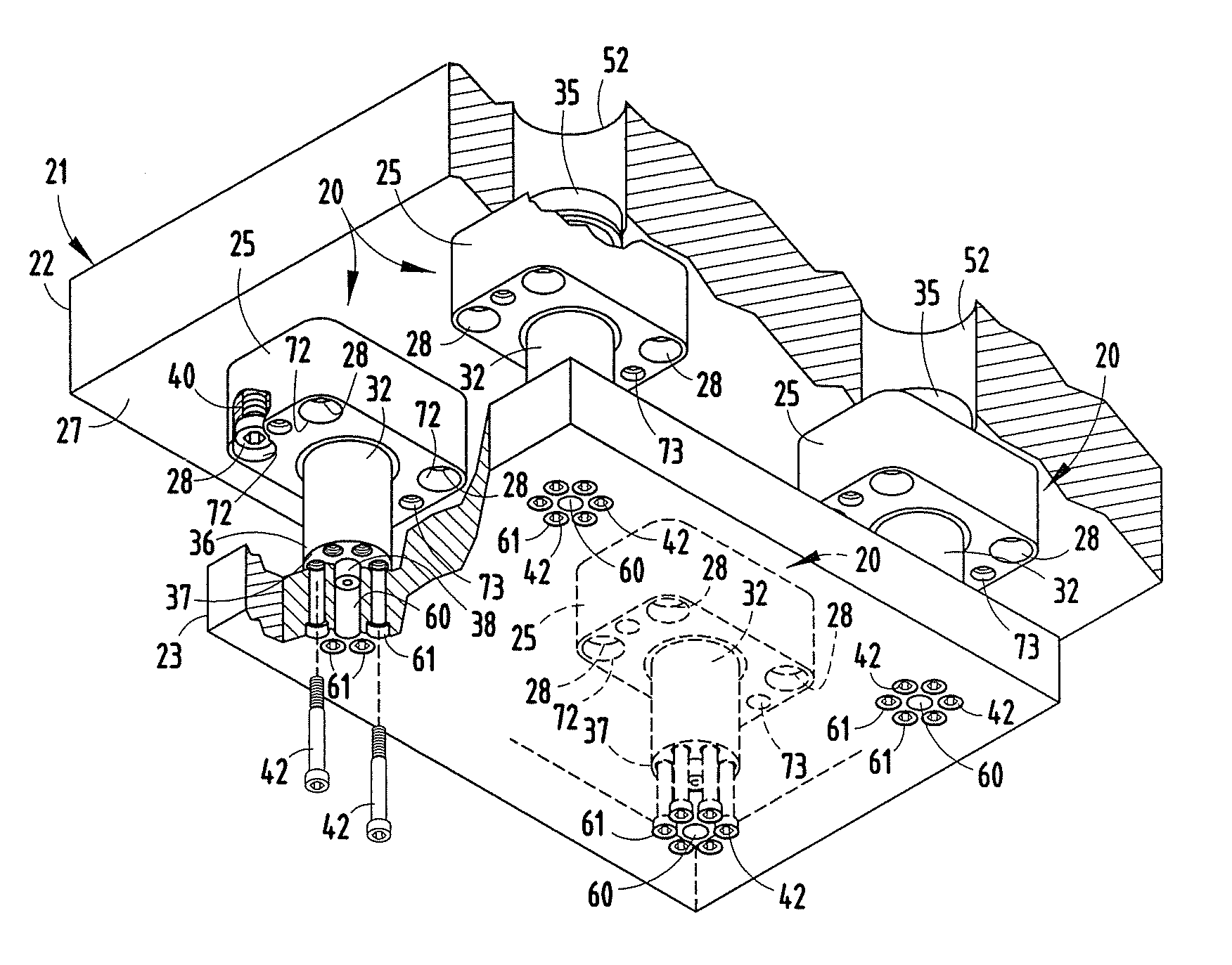
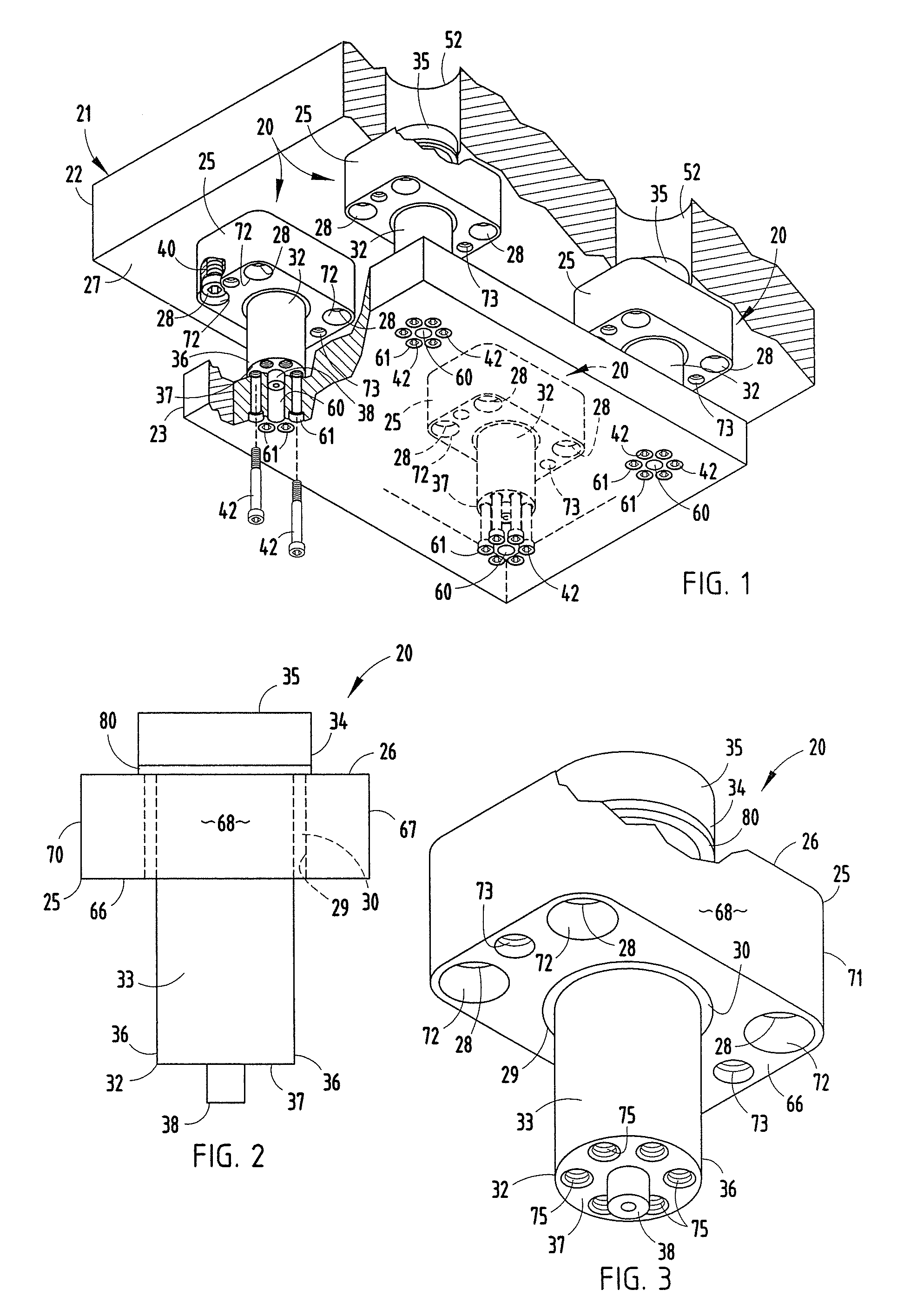
[0038]The reference numeral 20 (FIGS. 1-3) generally designates a guided keeper assembly embodying the present invention, which is particularly adapted for use in conjunction with metal forming dies...


PUM

PropertyMeasurementUnit
distanceaaaaaaaaaa
sizeaaaaaaaaaa
speedsaaaaaaaaaa

Abstract

A guided keeper assembly for metal forming dies includes a base having a mounting face and a fastener aperture to mount the base to an associated die shoe, as well as a central guide aperture. A guide pin having a central portion is closely received in the central guide aperture for precisely guiding reciprocal motion between the die pad and the die shoe. The guide pin has an enlarged head at one end which abuts the base to positively limit travel between the die shoe and the die pad, and a shoulder at an opposite end with an alignment mechanism that precisely locates the guide pin on the die pad. A fastener extends through the fastener aperture in the base to securely connect the same with the die shoe. Another fastener securely connects the second end of the guide pin with the die pad.

Description

CROSS REFERENCE TO RELATED APPLICATIONS AND CLAIM TO PRIORITY[0001]The present application is a continuation of commonly assigned, pending U.S. patent application Ser. No. 13 / 311,831 filed Dec. 6, 2011 (now U.S. Pat No. 8,522,595), which is a continuation of U.S. patent application Ser. No. 13 / 114,208 filed May 24, 2011 (now U.S. Pat. No. 8,074,486), which is a divisional of commonly assigned U.S. patent application Ser. No. 12 / 762,400 filed Apr. 19, 2010 (now U.S. Pat. No. 7,950,262), which is a continuation of commonly assigned U.S. patent application Ser. No. 11 / 515,477 filed Sep. 1, 2006 (now U.S. Pat. No. 7,730,757), which are incorporated herein by reference, and claim priority thereto under 35 U.S.C. §120.BACKGROUND OF THE INVENTION[0002]The present invention relates to metal forming dies and the like, in particular, to a guided keeper assembly and associated method.[0003]Metal forming dies, such as stamping dies and the like, are well known in the art. Progressive metal form...

Claims


Application Information

Patent Timeline
Patent Type & Authority Patents(United States)
IPC IPC(8): B21D37/04B21D37/08B21D37/10
CPCB21D37/04B21D37/10B21D37/08B21D37/02B21D22/10B21D37/12B21D37/14
Inventor PYPER, JOEL T.BREEN, SCOTT M.CHAISSON, GORDON L.YODER, JEREMIE J.MCINTYRE, THEODORE A.
Owner STANDARD LIFTERS INC
Why Eureka
Try Eureka