Method of controlling a motorized window treatment

a motorized window treatment and motor technology, applied in the direction of dynamo-electric converter control, dc motor rotation control, instruments, etc., can solve the problems of microprocessor reset, microprocessor reset, position information maintained by the microprocessor may become inaccurate, etc., to increase the amount of current and decrease the amount of current supplied

Active Publication Date: 2010-11-23
LUTRON TECH CO LLC
View PDF19 Cites 878 Cited by
  • Summary
  • Abstract
  • Description
  • Claims
  • Application Information

AI Technical Summary

Problems solved by technology

Motor overload conditions and low-line conditions may cause the DC voltage of the internal power supply of the electronic drive unit to drop below the voltage level required by the microprocessor to remain operational, and thus, may cause the microprocessor to reset.
A transitory large current drawn from the power supply of the electronic drive unit may cause the DC voltage to drop below the regulated level and thus cause the microprocessor to reset.
If the microprocessor resets during movement of the roller shade, the position information maintained by the microprocessor may become inaccurate, which could also prevent the microprocessor from moving the shade fabric.

Method used


Image

  • Method of controlling a motorized window treatment
  • Method of controlling a motorized window treatment
  • Method of controlling a motorized window treatment

Examples


first embodiment

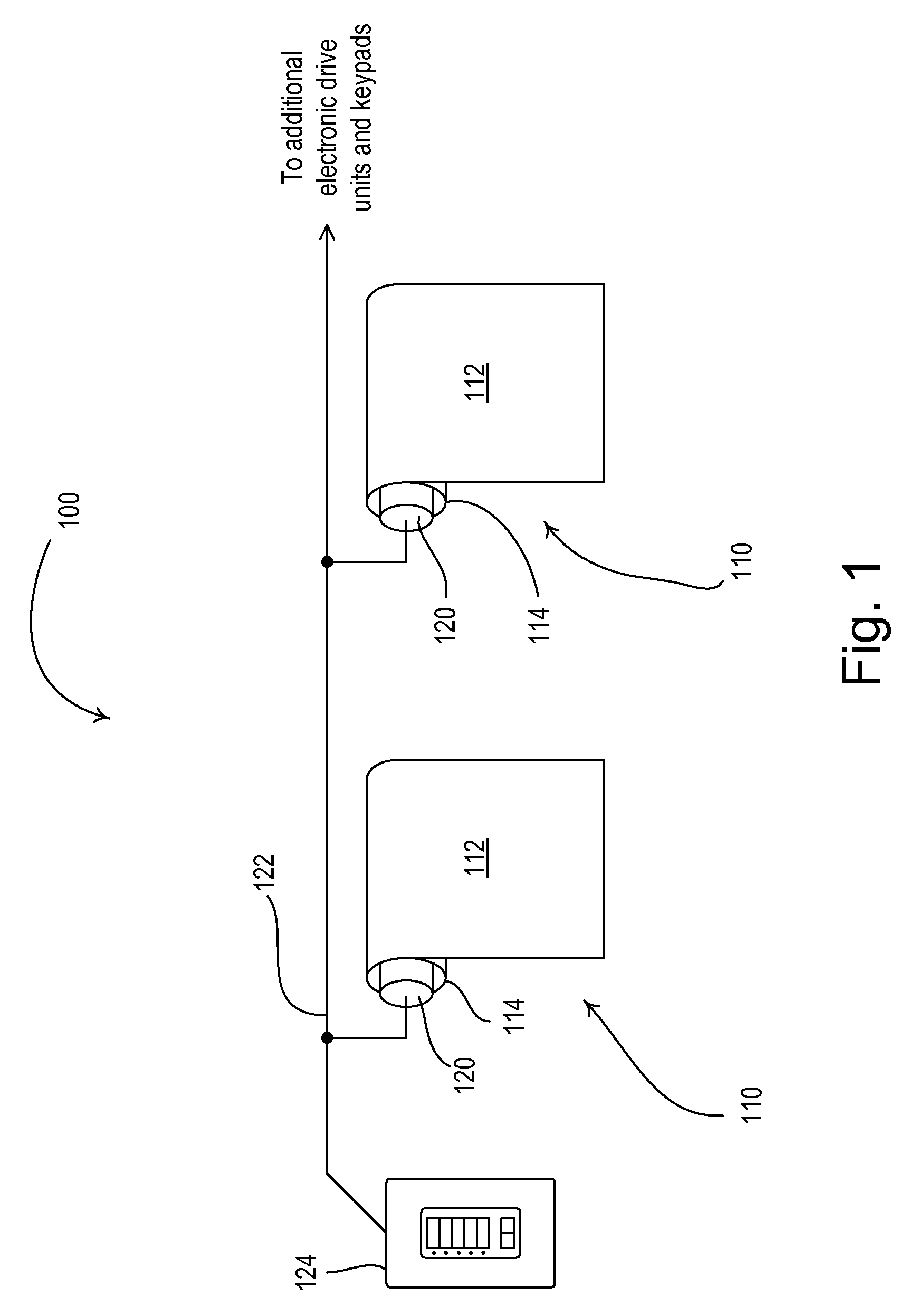
[0036]FIG. 1 is a simplified block diagram of the motorized window treatment control system 100 according to the present invention. The motorized window treatment control system 100 comprises a plurality of motorized window shades 110, which each comprise a flexible shade fabric 112 rotatably supported by a roller tube 114. The motorized window treatments 110 are controlled by electronic drive units (EDUs) 120, which may be located inside the roller tubes 114. The electronic drive units 120 are operable to control the shade fabrics 112 between an open position and a closed position. The EDUs 120 are coupled to a communication link 122 and are operable to receive commands across the communication link from a keypad 124. The communication link 122 may comprise a wired communication link or a wireless communication link, such as, for example, a radio-frequency (RF) communication link or an infrared (IR) communication link. The control system 100 is described in greater detail in common...

second embodiment

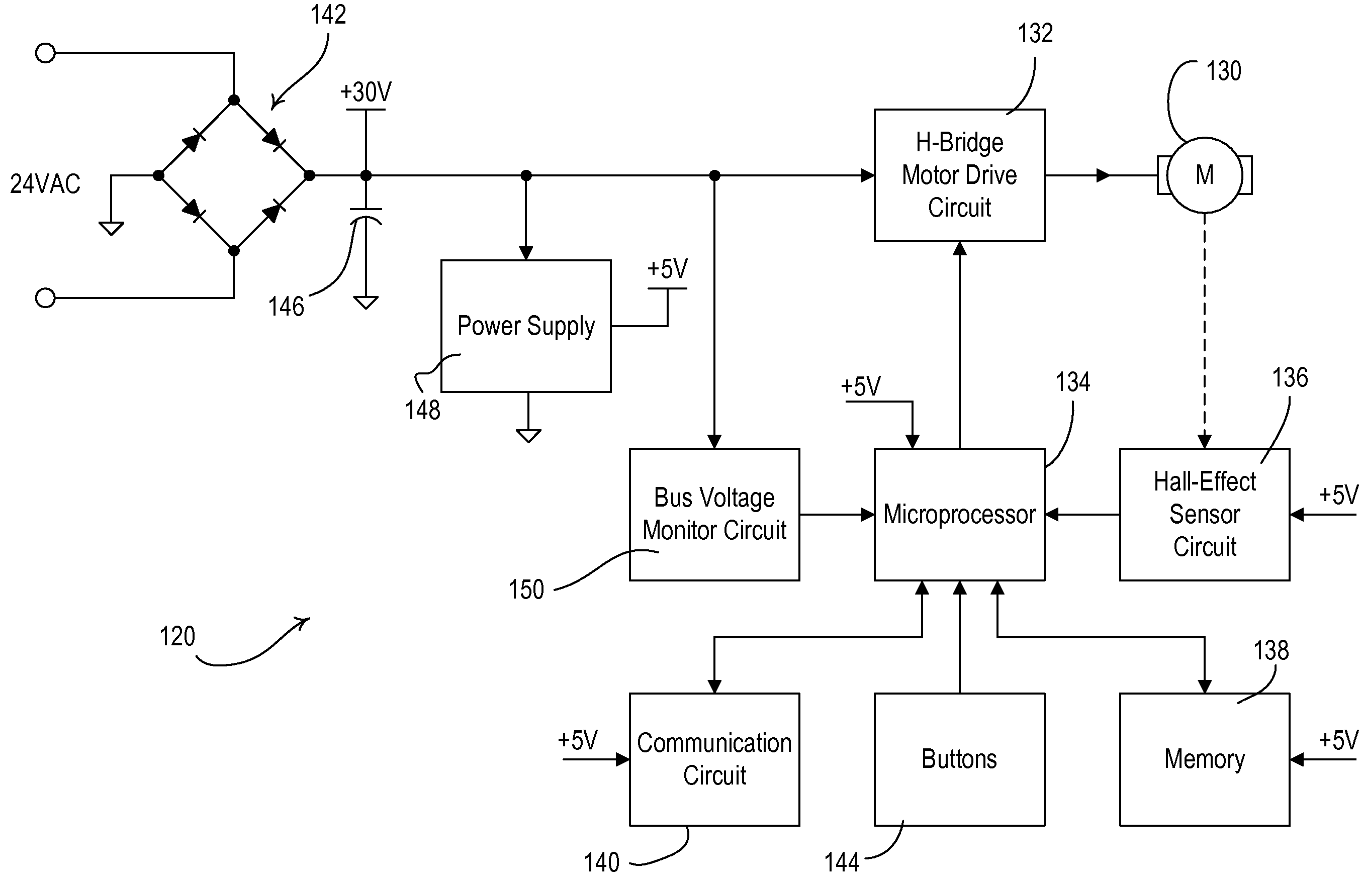
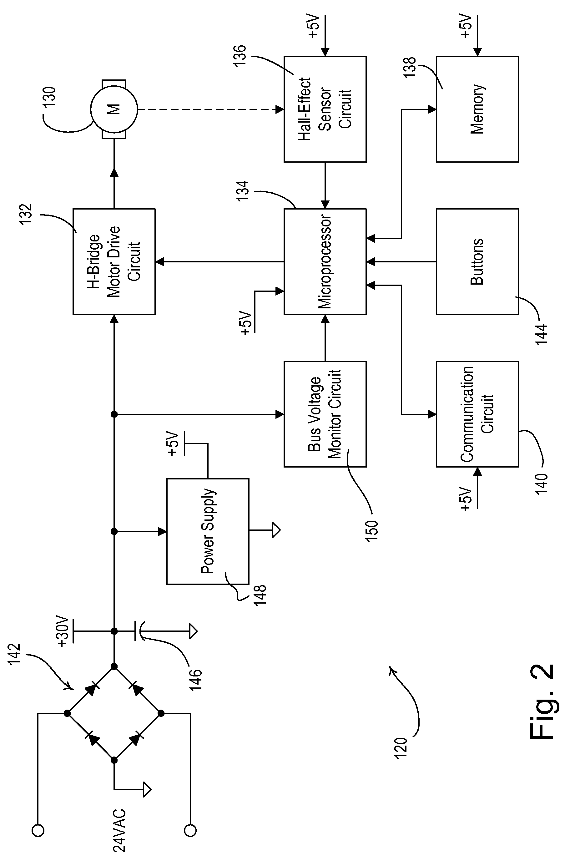
[0081]FIG. 10 is a simplified flowchart of a bus voltage monitor procedure 1020 executed periodically (e.g., every 572 μsec) by the microcontroller 134 according to the present invention. At step 1022, the microcontroller 134 samples the control signal BUS_MNTR. If the bus voltage VBUS is less than or equal to the first voltage threshold VTH1 at step 1024, the controller 134 stores the present duty cycle of the PWM signal driving the H-bridge motor drive circuit 132 at step 1025 and sets the OVERLOAD flag at step 1026. Next, the controller 134 begins to decrease the duty cycle of the PWM signal driving the H-bridge motor drive circuit 132. Specifically, microcontroller 134 calculates the difference VDIFF between the actual magnitude of the bus voltage VBUS and a desired overload magnitude (e.g., approximately 20 V) at step 1028, and determines the desired duty cycle DC of the PWM signal in response to the difference VDIFF at step 1030, e.g., by using the equation

DC=α·VDIFF+DCTYP  (E...

third embodiment

[0083]FIG. 11 is a simplified flowchart of a bus voltage monitor procedure 1120 executed periodically (e.g., every 572 μsec) by the microcontroller 134 according to the present invention. The bus voltage monitor procedure 1120 is identical to the bus voltage monitor procedure 520 of FIG. 5B, except that the microcontroller 134 now decreases the amount of current delivered to the motor by storing the present duty cycle of the PWM signal in the memory 138 at step 1125 and then decreasing the duty cycle of the PWM signal to a predetermined duty cycle (e.g., 50%) at step 1126 rather than simply stopping the motor (i.e., at step 526 of FIG. 5B). Further, the microcontroller 134 increases the duty cycle of the PWM signal stored in the memory 138 at step 1136.


PUM


Abstract

A method of controlling a motorized window treatment provides for continued operation of the motorized window treatment during an overload or low-line condition. The motorized window treatment is driven by an electronic drive unit having a motor, a motor drive circuit, and a controller. The controller controls the motor drive circuit to drive the motor with a pulse-width modulated signal generated from a bus voltage. The controller is operable to monitor the magnitude of the bus voltage. If the bus voltage drops below a first voltage threshold, the controller stops the motor or reduces the duty cycle of the pulse-width modulated signal to allow the bus voltage to increase to an acceptable magnitude. When the bus voltage rises above a second voltage threshold, the controller begins driving the motor normally once again. During an overload or low-line condition, the controller is prevented from resetting, while driving the motor with minimal interruption to the movement of the motorized window treatment.

Description

RELATED APPLICATIONS[0001]This application claims priority from commonly-assigned U.S. Provisional Application Ser. No. 60 / 923,907, filed Apr. 17, 2007, entitled METHOD OF CONTROLLING A MOTORIZED WINDOW TREATMENT, the entire disclosure of which is hereby incorporated by reference.BACKGROUND OF THE INVENTION[0002]1. Field of the Invention[0003]The present invention relates to a method of controlling a motorized window treatment, and more specifically, a method of controlling a motorized roller shade during a motor overload or low-line condition.[0004]2. Description of the Related Art[0005]Motorized window treatments typically include a flexible fabric or other means for covering a window in order to block or limit the daylight entering a space and to provide privacy. The motorized window treatments may comprise, for example, roller shades, Roman shades, or draperies. The motorized window treatments include a motor drive for movement of the fabric in front of the window to control the...

Claims


Application Information

Patent Timeline
Patent Type & Authority Patents(United States)
IPC IPC(8): G05D3/00
CPCE06B9/68H02P7/0044H02P7/29H02P7/04
Inventor CARMEN, JR., LAWRENCE R.BRENNER, THOMAS WARRENLUNDY, STEPHEN
Owner LUTRON TECH CO LLC
Why Eureka
Try Eureka