Synchronous motor drive unit and a driving method thereof

a synchronous motor and drive unit technology, applied in the direction of motor/generator/converter stopper, electric generator control, electric devices, etc., can solve the problems of poor sensing accuracy of position shift, maintenance, and poor relationship between motor voltage and motor current, and achieve high maintainability and high-efficiency drive of synchronous motors.

Inactive Publication Date: 2006-06-15
HITACHI LTD
View PDF6 Cites 180 Cited by
  • Summary
  • Abstract
  • Description
  • Claims
  • Application Information

AI Technical Summary

Benefits of technology

[0016] According to a preferred embodiment of the present invention, even in case a rotary sensor with high maintainability is employed, degradation of

Problems solved by technology

If the resolver fails, however, engine unit or transmission unit must be removed from the vehicle and the unit be disassembled for repair.
Thus, maintainability has been a problem.
The technique in the Patent Document 1 involves a problem that time delay is caused in the d-q conversion of the motor voltage and motor current because the angle position after correction is employed and that the delay is easy to result in a significant error between the motor voltage and motor current and accordingly the sensing accu

Method used


Image

  • Synchronous motor drive unit and a driving method thereof
  • Synchronous motor drive unit and a driving method thereof
  • Synchronous motor drive unit and a driving method thereof

Examples


Embodiment Construction

[0035] A motor drive unit for vehicle according to an embodiment of the present invention is described hereunder, using drawing figures.

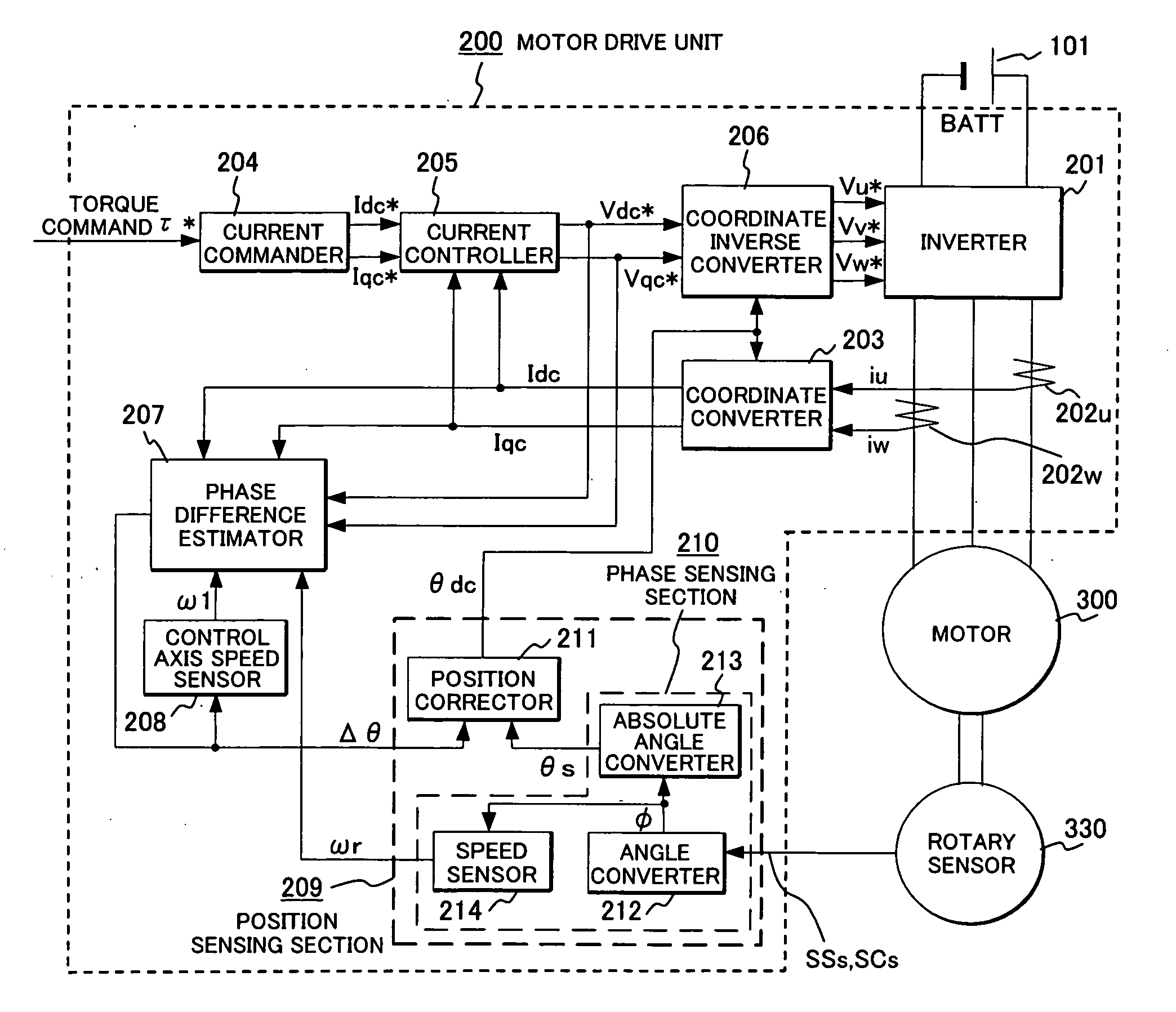
[0036]FIG. 1 is an overall control block diagram of a motor drive unit according to an embodiment of the present invention.

[0037] Power is supplied from a battery 101 to a permanent magnet synchronous motor (motor) 300 via a motor drive unit 200. The battery 101 serves as the DC power supply for the inverter 201 and power is converted into three-phase variable-voltage & variable-frequency AC by the inverter 201 and applied to the motor 300. DC voltage necessary for controlling the voltage to be applied to the motor 300 is sensed by a DC voltage sensor (not shown). Motor current sensor 202u, 202w sense the motor current necessary for computing the magnetic pole position. A rotor coordinate converter 203 converts the coordinate from the motor currents iu, iw sensed by the motor current sensors 202u, 202w based on the phase θdc of the virtual rotor p...


PUM


Abstract

A rotary sensor that outputs two analog signals, such as one sine wave and one cosine wave and has multiple periods within one period of the electrical angle of a motor is employed. The motor is energized at each position for a specified length of time upon its startup by using multiple electrical angles corresponding to the multiple candidate absolute angles obtained from the rotary sensor signal as the initial position of the motor, and the electrical angle at which the motor acceleration becomes maximum is determined as the absolute angle. While the motor drive is in operation, on the other hand, the phase difference Δθ between the phase of the motor at the counter electromotive voltage and the control phase is directly computed from the parameters of the motor, sensed current, voltage command and angle speed so as to correct the shifted position. A high-efficiency motor drive unit with improved maintainability of rotary sensor and improved accuracy of sensing the magnet pole position of a permanent magnet synchronous motor that accelerates and decelerates very quickly in a wide range of speed is realized.

Description

CLAIM OF PRIORITY [0001] The present application claims priority from Japanese application serial No. 2004-358115, filed on Dec. 10, 2004, the content of which is hereby incorporated by reference into this application. FIELD OF THE INVENTION [0002] The present invention relates to a synchronous motor drive unit and driving method thereof using rotary sensor, particularly to ones suitable for an application of the motor that accelerates and decelerates from zero speed (standing) up to high speed. BACKGROUND OF THE INVENTION [0003] One of the methods of driving a synchronous motor (hereinafter simply called as motor) is to employ position sensor for sensing the magnetic pole position of rotor. Position sensor in this description means ones including resolver or absolute encoder that cannot only sense the rotating angle in rotation but also determine the absolute position in standing. In order to drive a motor efficiently, however, matching the position sensor with the counter electrom...

Claims


Application Information

Patent Timeline
IPC IPC(8): H02P1/46H02P21/00H02P27/04H02P21/18H02P21/22H02P21/24H02P21/28H02P21/34H02P23/12H02P23/16H02P23/18H02P25/022
CPCB60K6/26B60K6/48B60L15/025B60L2220/14H02P1/46H02P21/0035Y02T10/6221Y02T10/643B60L15/20B60L2220/16B60L2240/421B60L2240/423B60L2240/427B60L2240/429H02P21/22Y02T10/72B60L50/16Y02T10/64Y02T10/62Y02T10/7072Y02T10/70
Inventor AJIMA, TOSHIYUKIMIYAZAKI, HIDEKIKAWABATA, YUKIOSAKAMOTO, KIYOSHIYANAI, TAKAOKOIZUMI, OSAMU
Owner HITACHI LTD
Why Eureka
Try Eureka