System and method for driving multiple pumps electrically with a single prime mover

a technology of prime mover and electrical drive, which is applied in the direction of pump control, positive displacement liquid engine, pump, etc., can solve the problems of busy and crowded pumping structur

Inactive Publication Date: 2015-07-30
GENERAL ELECTRIC CO
View PDF16 Cites 174 Cited by
  • Summary
  • Abstract
  • Description
  • Claims
  • Application Information

AI Technical Summary

Problems solved by technology

This technique employs many engines, gearboxes and pumps on many trailers, resulting in a very busy and very crowded pumping structure.

Method used


Image

  • System and method for driving multiple pumps electrically with a single prime mover
  • System and method for driving multiple pumps electrically with a single prime mover
  • System and method for driving multiple pumps electrically with a single prime mover

Examples


Embodiment Construction

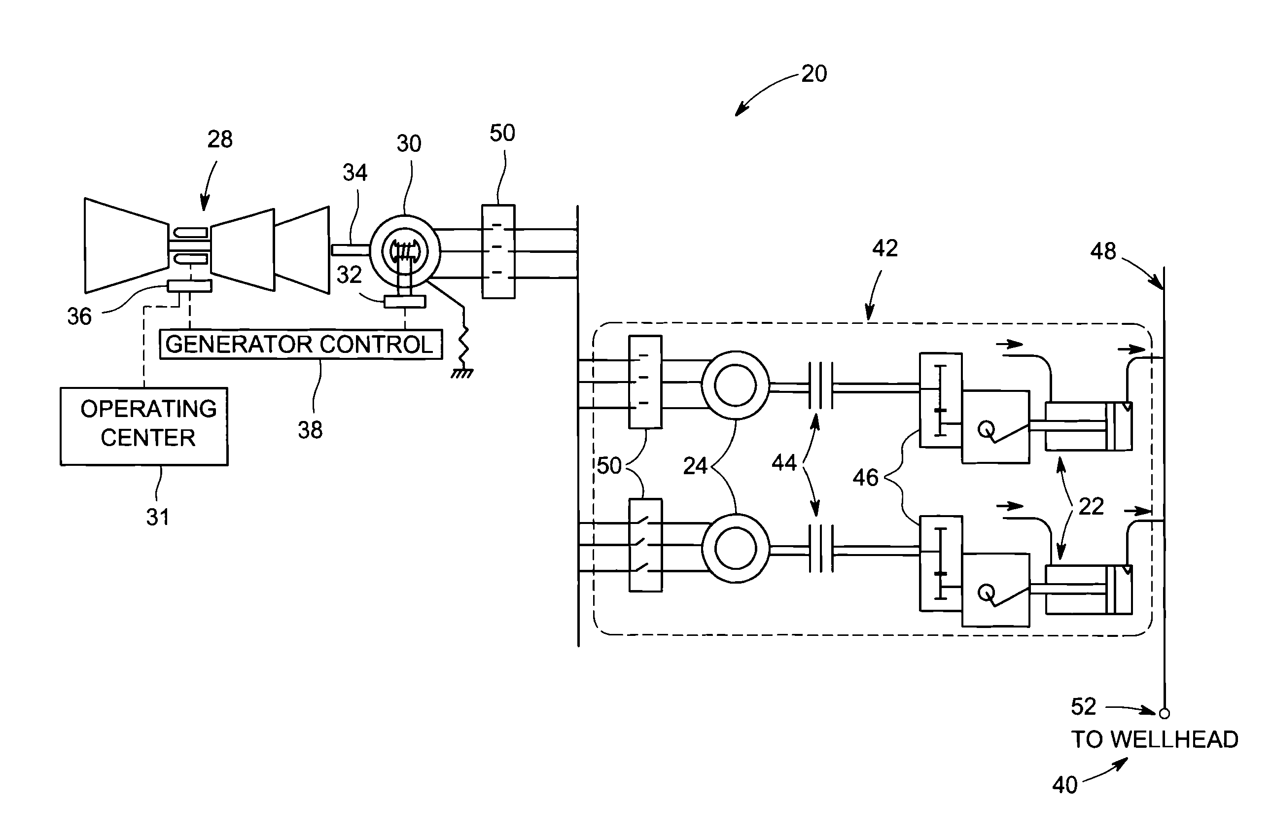
[0024]The embodiments described herein are directed to control of motor-driven pumps in applications that are operating independently of a utility power grid, and combine the control of a single prime mover and one or more AC or DC generators to provide electric power to a plurality of motor-driven pumps in a manner that reduces system complexity, cost and footprint size. Such embodiments are particularly useful in the gas fracking industry where the usual control objective is to regulate wellhead pressures and / or flow rates.

[0025]FIG. 3 is a motor-driven pumping system 20 illustrating a plurality of motor-driven pumps 22, according to one embodiment. Each pump 22 is driven by a corresponding electric motor 24. The electric motors 24 are powered from a shared electrical bus 26 that is supplied by a single prime mover 28 mechanically coupled to one or more electric generators 30. Although shown as an AC powered system, the principles described herein are just as easily applied to a D...


PUM


Abstract

A converterless motor-driven pump system includes an off-grid prime mover. The prime mover includes a rotational driveshaft that operates in response to a throttle or fuel input controller to control a rotation speed of the prime mover driveshaft. Operation of the throttle or fuel input controller is based on desired output characteristics of a pumping load. One or more electric power generators are driven by the off-grid prime mover to generate AC or DC power on an electrical bus shared by a plurality of variable speed electric motors. A plurality of pumps is connected to a common manifold shared by the plurality of pumps. The plurality of pumps is driven by the plurality of variable speed electric motors to generate a desired wellhead pressure or pumping load flow rate via the shared common manifold.

Description

BACKGROUND[0001]The subject matter of this disclosure relates generally to motor-driven pumps, and more particularly, to a multiplicity of motor-driven pumps being fed from a singularity of generators tied to a single, throttle controlled prime mover.[0002]A common way to drive multiple pumps uses multiple prime movers. The gas fracking industry, for example, generally employs a single diesel engine powering a single pump through a mechanical gear box. This technique employs many engines, gearboxes and pumps on many trailers, resulting in a very busy and very crowded pumping structure.[0003]FIG. 1 illustrates a conventional system 1 that is known in the gas fracking industry for operating a pump. The system 1 uses a single prime mover including a diesel engine 2 that is fueled by either natural gas or diesel fuel to drive a fracking pump 3. Each fracking pump 3 is mechanically coupled via a transmission and corresponding gearbox 5 to a single reciprocating pump 3 to achieve optimiza...

Claims


Application Information

Patent Timeline
Patent Type & Authority Applications(United States)
IPC IPC(8): F04B49/20F04B23/06
CPCF04B23/06F04B49/20
Inventor WIEGMAN, HERMAN LUCAS NORBERTGEMIN, PAUL ROBERTROSS, BENJAMIN EARLSANBORN, STEPHEN DUANEMCDOWELL, ROBERT EARL
Owner GENERAL ELECTRIC CO
Why Eureka
Try Eureka