Coupling system for an infusion pump

a coupling system and infusion pump technology, applied in the direction of tube connectors, instruments, other medical devices, etc., can solve the problems of insufficient dexterity of users, inconvenient operation, and inability to adjust the position of cartridges with respect to the drive system, so as to reduce the size of the infusion pump and improve portability

Inactive Publication Date: 2005-01-27
INOUE YOSHIO +4
View PDF4 Cites 186 Cited by
  • Summary
  • Abstract
  • Description
  • Claims
  • Application Information

AI Technical Summary

Benefits of technology

[0010] One advantage of at least one embodiment of the present invention is that a syringe is coupled to a pump housing in the same movement as a drive nut of the drive system is coupled to a piston of the syringe.
[0011] Another advantage of at least one embodiment of the present invention is that it reduces the size of an infusion pump for improved portability.
[0012] Another advantage of at least one embodiment of the present invention is that occlusions in an infusion line are detected.
[0013] Yet another advantage of at least one embodiment of the present invention is that the ravel of the drive mechanism is detected.

Problems solved by technology

In conventional systems, this is often a complex operation, requiring considerable dexterity on the part of the user.
If the cartridge insertion operation is not performed correctly, the cartridge may be improperly positioned with respect to the drive system, and inaccurate dosages administered as a result.

Method used


Image

  • Coupling system for an infusion pump
  • Coupling system for an infusion pump
  • Coupling system for an infusion pump

Examples


Embodiment Construction

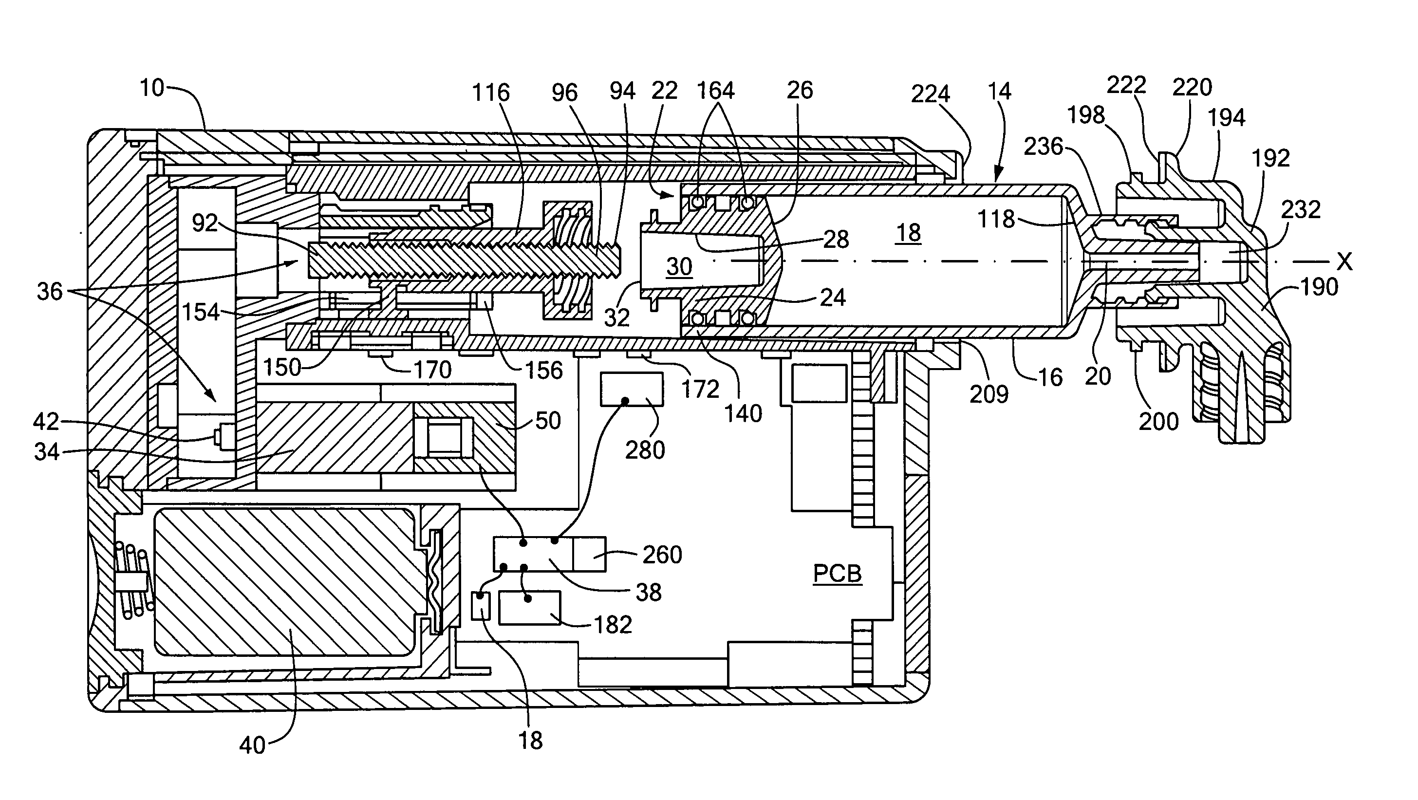
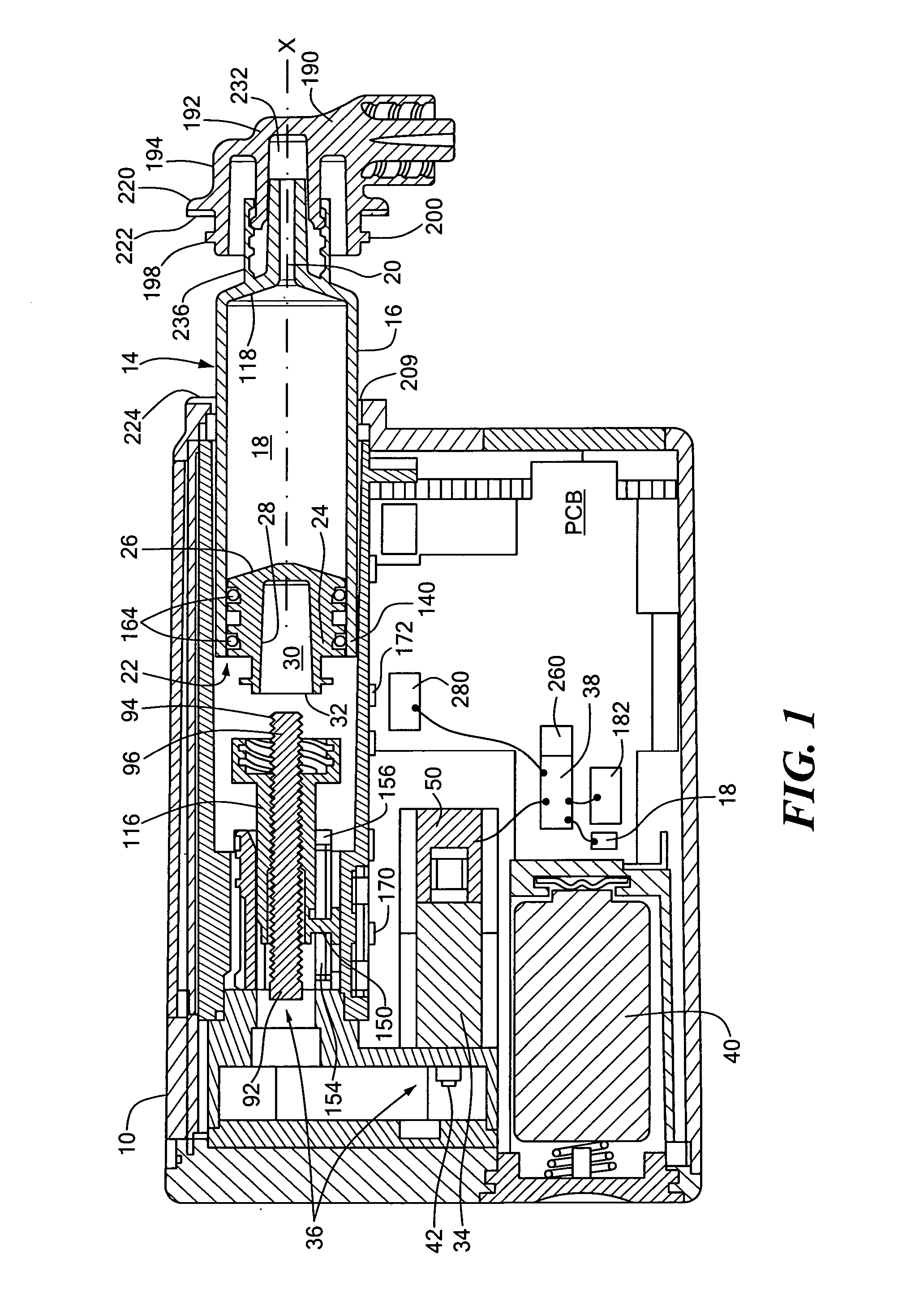
[0053] With reference to FIG. 1, a portable pump system for use in an ambulatory injection system, such as an insulin injection system, is shown. The system includes a housing 10, which is designed to fit conveniently in the pocket of a user or to be attached to a belt clip. A cassette 14, such as a disposable or reusable syringe, is selectively received within the housing 10. FIG. 1 shows the syringe 14 partially inserted into the housing 10. The syringe 14 holds a supply of a medicament, such as insulin, for injection into a diabetic patient, or other user in need of the medicament. The syringe 14 includes a barrel 16, which defines an internal chamber 18 for holding the medicament, a dispensing outlet 20 in fluid communication with the internal chamber and connected with one end of the barrel 16, and an opening 22 at an opposite end of the barrel 16. A plunger or piston 24 is received within the barrel 16 via the opening 22 for reciprocal motion within the barrel 16 for selective...


PUM


Abstract

A pump system for an infusion system includes a linear drive (36, 36′) which minimizes the space occupied by the pump components in a portable housing (10, 10′). A motor (34) and a motor drive shaft (42) are arranged in parallel with, and adjacent to a syringe (14, 14′) and lead screw (94, 94′). A gear box (54) connects the drive shaft and lead screw to transfer rotational movements between them. A piston driving member, such as a drive nut (116) converts the rotational movement of the lead screw into linear motion of a syringe piston (24). A cap (190, 190′) couples the syringe (14, 14′) to the housing and provides an outlet for the liquid to be dispensed. In one embodiment, the cap (190′) is configured to rotate relative to the housing in one direction only, during locking. Rotational movement is also used for locking the piston (24) to the drive nut (116) against relative axial movement. In another embodiment, the cap (190′) carries a rotatable hub (330) which is connected at a first end (336) with an infusion line (191) and at a second end defines a needle (338) for piercing a closure (340) on the syringe.

Description

CROSS-REFERENCE TO RELATED APPLICATION [0001] This application is related to and claims priority to U.S. Provisional Patent Application Ser. No. 60 / 476,973, filed Jun. 09, 2003, entitled COUPLING SYSTEM FOR AN INFUSION PUMP, which application claims the priority of U.S. application Ser. No. 10 / 121,318, filed Apr. 12, 2002, entitled DRIVE SYSTEM FOR AN INFUSION PUMP, which is incorporated herein in its entirety by reference, and U.S. Provisional Application Ser. No. 60 / 283,815, filed Apr. 13, 2001, also incorporated herein in its entirety by reference, the entirety of all of which is incorporated herein by reference.STATEMENT REGARDING FEDERALLY SPONSORED RESEARCH OR DEVELOPMENT [0002] n / a FIELD OF THE INVENTION [0003] The present invention relates to a method and system for delivering medicament, such as insulin, from a syringe, and more particularly, to a portable pump having a coupling system for allowing the syringe to be locked to a syringe housing and a piston of the syringe to...

Claims


Application Information

Patent Timeline
Patent Type & Authority Applications(United States)
IPC IPC(8): A61MA61M1/00A61M5/142A61M5/145A61M5/168A61M37/00A61M39/10
CPCA61M5/14244A61M5/14566A61M2205/3389A61M39/10A61M5/1685
Inventor INOUE, YOSHIORAMEY, KIRKSONODA, YOSHIYUKISOWELL, ROBERTWILLIAMS, ROBERT
Owner INOUE YOSHIO
Why Eureka
Try Eureka