Motor having controllable torque

a technology of electric motors and torque, applied in the direction of motor/generator/converter stoppers, electronic commutators, dynamo-electric converter control, etc., can solve the problems of unsatisfactory large weight and size increase, and achieve the effect of increasing siz

Inactive Publication Date: 2012-02-28
HONEYWELL INT INC
View PDF30 Cites 927 Cited by
  • Summary
  • Abstract
  • Description
  • Claims
  • Application Information

AI Technical Summary

Problems solved by technology

Sizing and aligning each winding for a highly unlikely event where high load and corresponding additional torque is demanded from the motor may necessitate an undesirable large weight and size increase.

Method used


Image

  • Motor having controllable torque
  • Motor having controllable torque
  • Motor having controllable torque

Examples


Embodiment Construction

[0009]The following detailed description is merely exemplary in nature and is not intended to limit the invention or the application and uses of the invention. Furthermore, there is no intention to be bound by any theory presented in the preceding background or the following detailed description.

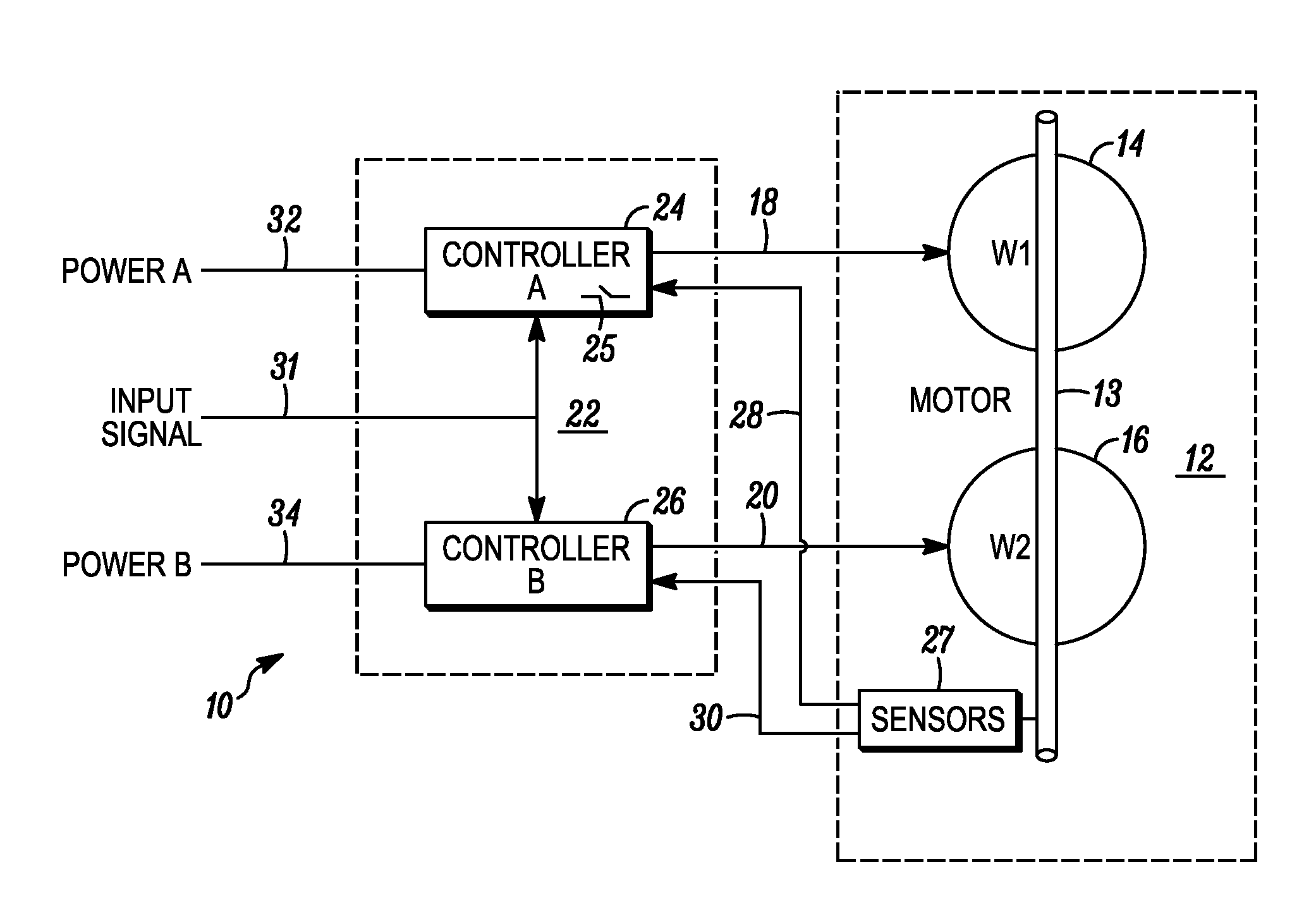
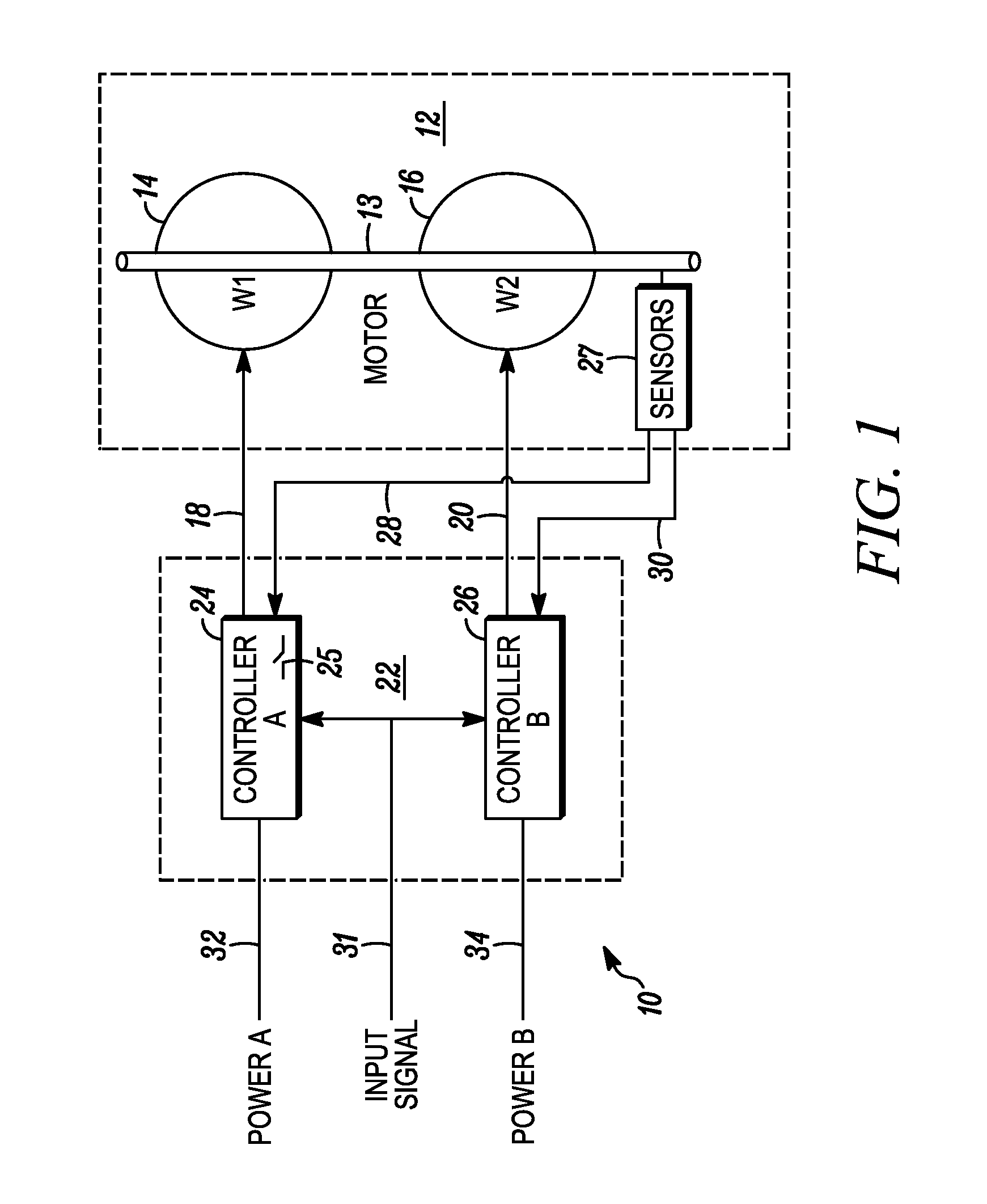
[0010]Turning to FIG. 1, an exemplary embodiment of a system 10 that provides controllable torque is shown. System 10 includes a motor 12 and a motor control 22. The motor includes a rotor 13, a first stator winding set 14 (denoted by W1) and a second stator winding set (denoted by W2). Although the primary and secondary winding sets are shown conceptually apart, in practice, the primary and second winding sets may be wound coaxially with respect to the rotor 13. Each winding set 12, 14 may be variably wound. For example, in a three-phase embodiment, the winding sets may be connected in a delta or wye configuration.

[0011]Motor control 22 is implemented as a dual-channel control and selective...


PUM


Abstract

A controllable motor includes a rotor. A first stator winding set is operable, upon being energized, to generate and apply a first torque to the rotor. A second stator winding set independent of the first stator winding set is operable, upon being energized, to generate and apply a second torque to the rotor. A motor control is coupled to the first and second stator winding sets. The motor control is operable to selectively energize one of the first or second stator winding sets to thereby generate and apply one of the first or second torques to the rotor, and simultaneously energize both the first and second stator winding sets to thereby generate and apply a third torque greater than the first or the second torque.

Description

TECHNICAL FIELD[0001]The present invention relates to electric motors, and more specifically, to electric motors having controllable torque.BACKGROUND[0002]Electric motors are commonplace in today's society. Motors of various types and sizes are used in numerous settings. Some electric motors incorporate a set of redundant motor windings to provide a backup mechanism in the highly unlikely event that the set of first motor windings becomes inoperable. Such redundant winding sets may be found in various applications such as in aerospace environments.[0003]For electric motors with redundant motor winding sets, it is desirable to size each winding set for the full range of performance duty cycles during normal motor operation. Doing so results in full performance being available from either winding set in the highly unlikely event that one set becomes inoperable. Sizing and aligning each winding for a highly unlikely event where high load and corresponding additional torque is demanded...

Claims


Application Information

Patent Timeline
Patent Type & Authority Patents(United States)
IPC IPC(8): H02P6/00
CPCH02P6/14
Inventor JOHNSON, ANDREW T.HANLON, CASEY
Owner HONEYWELL INT INC
Why Eureka
Try Eureka