
Built-in cooling device of high-speed rotary main shaft

A high-speed rotation and cooling device technology, which is applied to metal processing machinery parts, maintenance and safety accessories, metal processing equipment, etc., can solve the problems of increased volume and weight, complex mechanical structure of the spindle, and increased cost.

Inactive Publication Date: 2010-10-27
上海舒平精工机械有限公司
View PDF0 Cites 10 Cited by
  • Summary
  • Abstract
  • Description
  • Claims
  • Application Information

AI Technical Summary

Problems solved by technology

[0004] 1. The mechanical structure of the main shaft of the water cooling device is complicated, and the volume and weight have increased
[0005] 2. The water cooling device needs a special water cooling pump, which increases the cost

Method used


Image

  • Built-in cooling device of high-speed rotary main shaft
  • Built-in cooling device of high-speed rotary main shaft
  • Built-in cooling device of high-speed rotary main shaft

Examples


Embodiment Construction

[0027] The built-in cooling device for the high-speed rotating spindle of the present invention will be described in detail below with reference to the accompanying drawings.

[0028] The invention provides two embodiments.

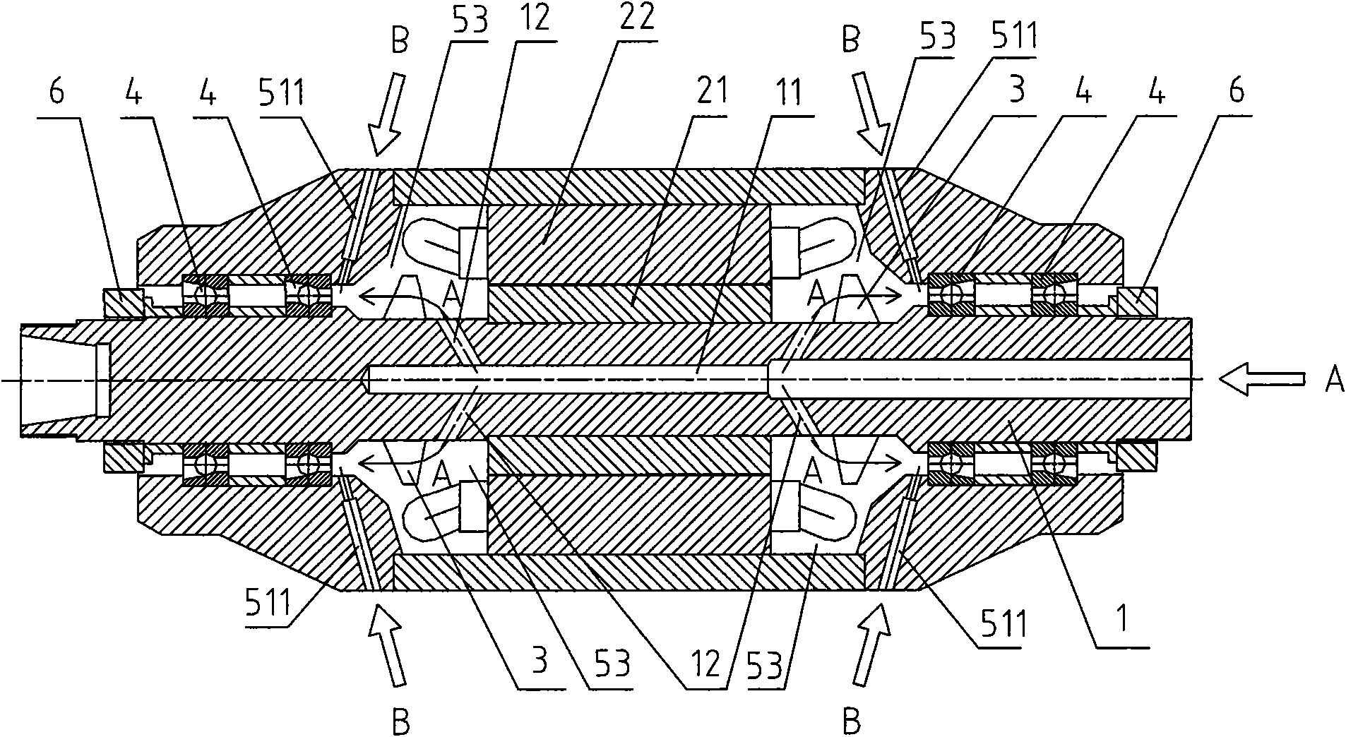
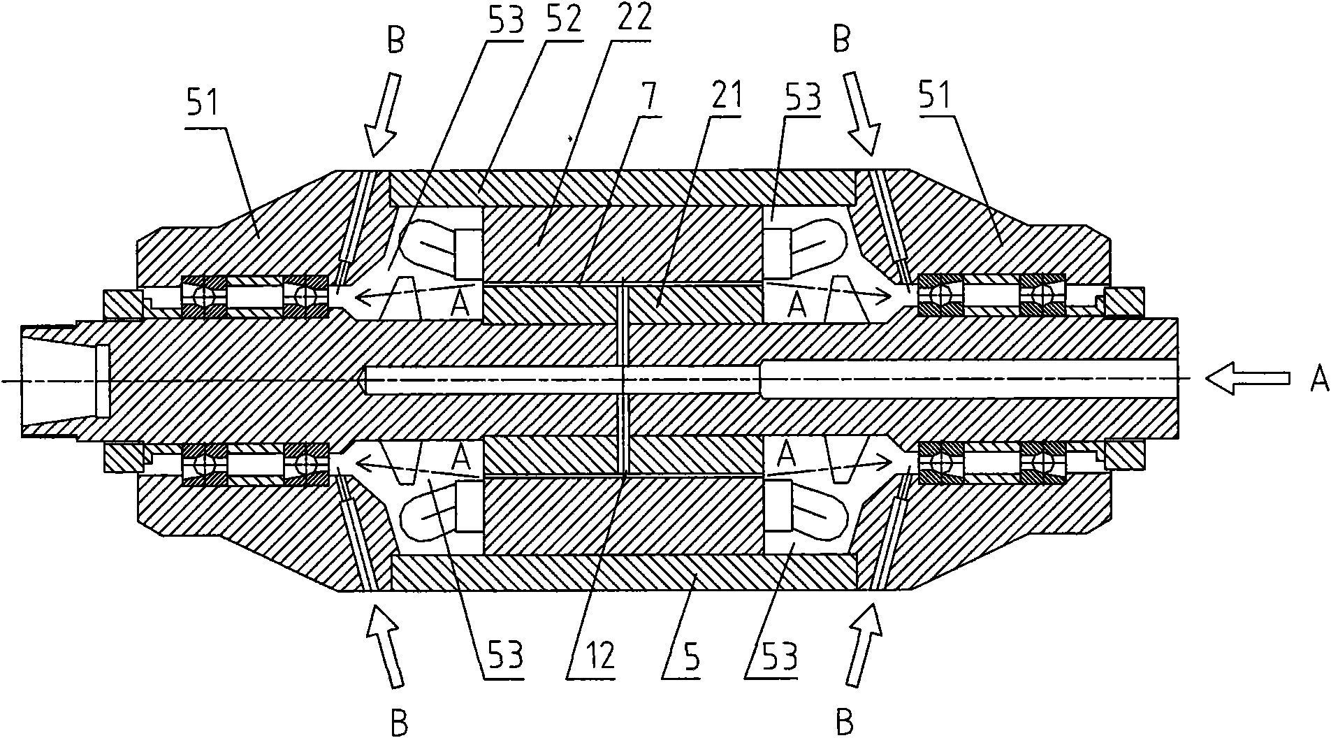
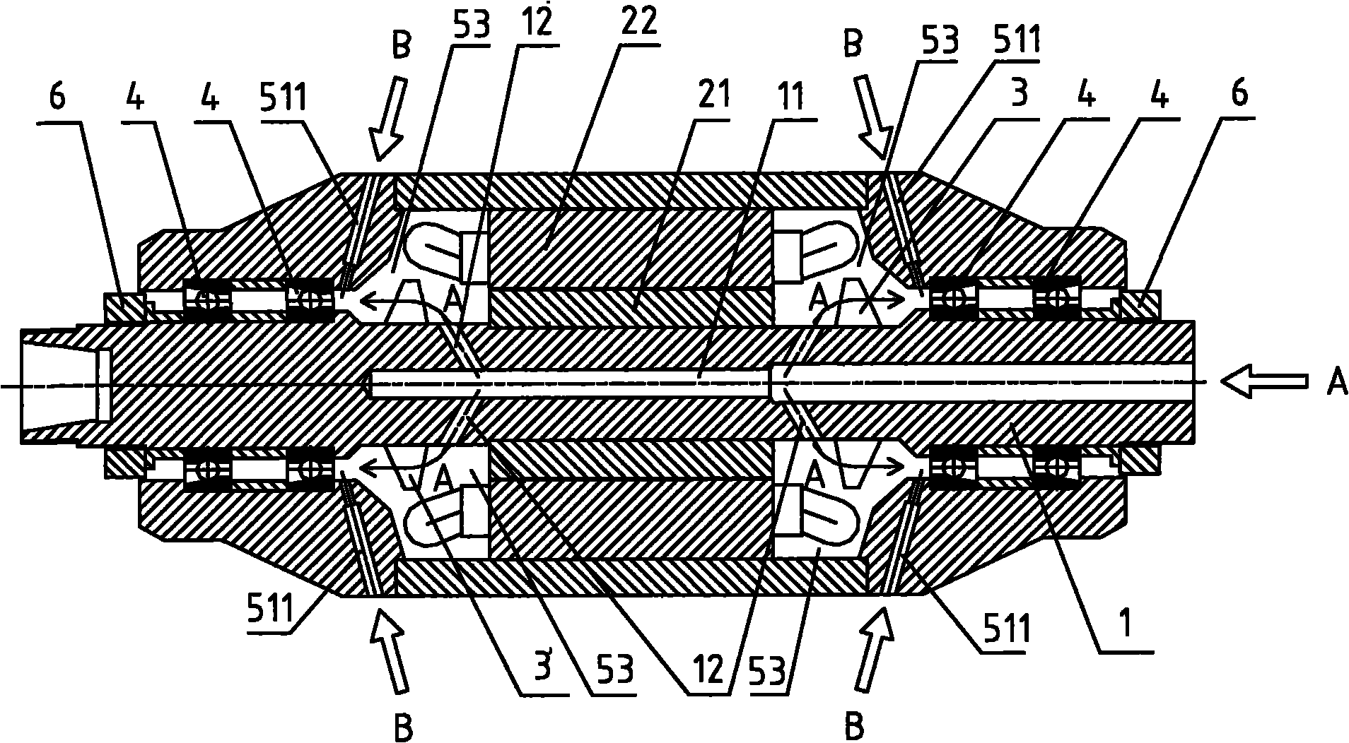
[0029] Embodiments of the present invention are as figure 1 As shown, the present invention includes a main shaft 1 that rotates at a high speed during use, a magnet 21 is sleeved in the middle of the main shaft 1 , and an electromagnetic coil 22 is sleeved on the magnet 21 . The magnet 21 and the electromagnetic coil 22 constitute a drive motor of the spindle 1 . Both the bearing 4 and the electromagnetic coil 22 are arranged in the main shaft housing 5 . The inner cavity 53 of the spindle housing 5 is formed between the bearing 4 , the electromagnetic coil 22 and the magnet 21 .

[0030] The main shaft housing 5 includes a main shaft shell 52 located in the middle and main shaft end housings 51 located at both ends. The main shaft end shell 51 is co...


PUM


Abstract

The invention discloses a built-in cooling device of a high-speed rotary main shaft, which comprises a main shaft (1), wherein a bearing (4) is respectively arranged at two ends of the main shaft (1); a magnet (21) is sleeved in the middle of the main shaft (1); an electromagnetic coil (22) is sleeved outside the magnet (21); each bearing (4) and the electromagnetic coil (22) are arranged in a main shaft shell (5); an inner cavity (53) of the main shaft shell (5) is formed between each bearing (4) and the electromagnetic coil (22) as well as the magnet (21); a blow hole (11) is arranged in the main shaft (1) in an axial direction; and the blow hole (11) is communicated with the inner cavity (53) of the main shaft shell (5) through a communicating hole (12). When the built-in cooling device is used, air is blown from the blow hole in the main shaft, air flow passes through the communicating hole to be blown to an impeller, and the impeller blows the air flow to the bearings, thereby performing the function of cooling the bearings; and simultaneously, lubricating oil or oil mist is sprayed from an oil spray hole, the air flow blown from the impeller can blow away the lubricating oil, and the lubricating oil is blown to the bearings, thereby performing the double functions of lubricating and cooling.

Description

technical field [0001] The invention relates to a cooling device, in particular to a built-in cooling device for a high-speed rotating spindle. Background technique [0002] Most of the existing high-speed rotating spindles above 30,000rpm use water cooling devices. [0003] Compared with the air cooling method, the existing water cooling device has the following disadvantages: [0004] 1. The mechanical structure of the main shaft of the water cooling device is complicated, and the volume and weight are increased. [0005] 2. The water cooling device needs a special water cooling pump, which increases the cost. [0006] So far, regardless of whether it is water-cooled or air-cooled, the high-speed rotating spindle is cooled from the outside. Therefore, we invented a new air cooling device. Contents of the invention [0007] The technical problem to be solved by the present invention is to provide a built-in cooling device for a high-speed rotating spindle with better ...

Claims


Application Information

Patent Timeline
IPC IPC(8): B23Q11/12B23B19/02
Inventor 杨岚
Owner 上海舒平精工机械有限公司
Learn More