Porous array lubricating device for high-speed rolling bearing

A technology of porous array and lubricating device, which is applied to rolling contact bearings, rotating bearings, bearings, etc., can solve problems such as affecting the working performance of the transmission system, damage to the performance of the bearing, wear and anxiety of the inner ring, etc., to improve the service life. and working performance, uniform lubrication, avoiding the effect of too little lubricating oil

Inactive Publication Date: 2017-02-15
BEIJING INSTITUTE OF TECHNOLOGYGY
View PDF6 Cites 10 Cited by
  • Summary
  • Abstract
  • Description
  • Claims
  • Application Information

AI Technical Summary

Problems solved by technology

When the rolling bearing is running at high speed, due to the effect of centrifugal force, the lubricating oil sprayed into the bearing will be thrown to the raceway of the outer ring of the bearing under the action of centrifugal force, so that the amount of lubricating oil in the inner ring of the bearing is reduced or even insufficient, and the inner ring of the bearing In high-speed rotation, the temperature of the inner ring of the bearing is much higher than that of the outer ring. If the temperature rise of the inner ring of the bearing is too high, it is easy to cause wear and scorching of the inner ring, which will damage the performance of the bearing and affect the performance of the entire transmission system.

Method used


Image

  • Porous array lubricating device for high-speed rolling bearing
  • Porous array lubricating device for high-speed rolling bearing
  • Porous array lubricating device for high-speed rolling bearing

Examples


Embodiment Construction

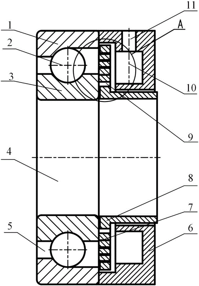
[0014] See attached figure 1 , 2 , a multi-hole array lubrication device for high-speed rolling bearings, comprising: an oil inlet sleeve 6 and an oil distribution sleeve 8;

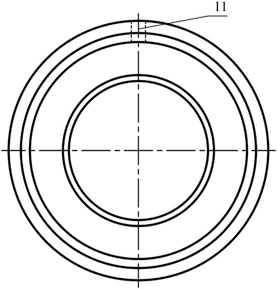
[0015] See attached figure 1 , 3 , the oil inlet sleeve 6 is provided with an annular oil storage chamber 10 and an oil inlet passage 11 communicating with the oil storage chamber 10;

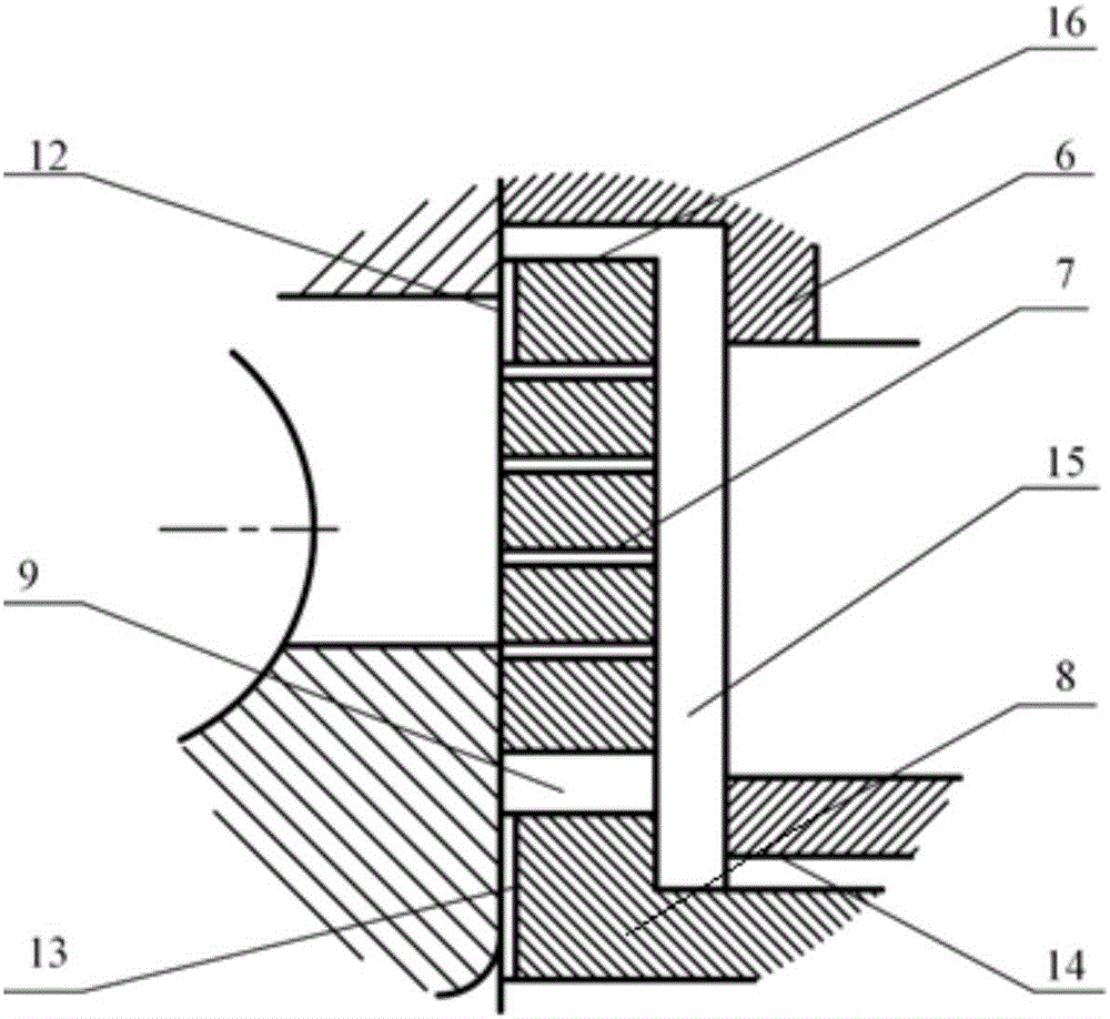
[0016] On the end surface of the oil distribution sleeve 8, there are a plurality of heat dissipation oil storage holes 9 of the inner ring and oil injection hole groups corresponding to the heat dissipation oil storage holes 9 of the inner ring evenly distributed along its circumferential direction; Figure 4 As shown: four oil injection holes 7 form a group; each oil injection hole group is arranged outside an inner heat dissipation oil storage hole 9, and the oil injection holes 7 in each group are arranged in a straight line (in the radial direction) at equal intervals ;

[0017] The oil distribution sleeve 8 is ...


PUM


Abstract

The invention belongs to the technical field of fluid lubrication, and particularly relates to a bearing lubricating device. According to the technical scheme adopted by the invention, a porous array lubricating device for a high-speed rolling bearing lubricating device is characterized in that an oil inlet sleeve is equipped with a ring-shaped oil storage cavity and an oil inlet path which communicates with the oil storage cavity; an oil distribution sleeve is equipped with circumferential inner ring radiating oil storage holes and oil spray holes which are arranged in the form of array; the oil distribution sleeve is connected on a main shaft in a sleeving mode; and the oil inlet sleeve is assembled with the oil distribution sleeve, and fits to one side of the rolling bearing. According to the porous array lubricating device, lubricating oil which enters the lubricating device can achieve the effects of spraying oil to lubricate, and also can keep certain lubricating oil amount of an inner ring of the rolling bearing; and the oil storage cavity in one side of the inner ring of the rolling bearing also can achieve the effects of cooling bearings. According to the lubricating device, oil spraying small holes are designed, so that lubricating oil lubricates the bearings in the form of mist, and therefore, lubricating oil amount can be reduced, lubricating is more uniform, and the temperature rise of the inner ring of the rolling bearing is lower.

Description

technical field [0001] The invention belongs to the technical field of fluid lubrication, in particular to a bearing lubrication device. Background technique [0002] The rolling bearings in the high-speed transmission of vehicles will generate a lot of heat when they run at high speed, which will cause the temperature rise of the bearings to be too high. Reasonable lubrication methods and devices can effectively take away the heat generated by the bearings and reduce the temperature rise of the bearings. When the rolling bearing is running at high speed, due to the effect of centrifugal force, the lubricating oil sprayed into the bearing will be thrown to the raceway of the outer ring of the bearing under the action of centrifugal force, so that the amount of lubricating oil in the inner ring of the bearing is reduced or even insufficient, and the inner ring of the bearing In high-speed rotation, the temperature of the inner ring of the bearing is much higher than that of t...

Claims


Application Information

Patent Timeline
Patent Type & Authority Applications(China)
IPC IPC(8): F16C33/66F16C37/00F16C19/52
CPCF16C33/6659F16C19/525F16C37/007F16C2326/01
Inventor 吴维陈卓群苑士华胡纪滨
Owner BEIJING INSTITUTE OF TECHNOLOGYGY
Why Eureka
Try Eureka