Head for thermal assisted magnetic recording device, and thermal assisted magnetic recording device

a recording device and magnetic recording technology, applied in the field of head for thermal assisted magnetic recording device, can solve the problems of reducing the efficiency of optical near field generation, deterioration of scatterer, etc., and achieve the effect of increasing the optical near field intensity, avoiding temperature rise of scatterer, and increasing the volume of scatterer

Inactive Publication Date: 2011-04-28
HITACHI LTD
View PDF12 Cites 45 Cited by
  • Summary
  • Abstract
  • Description
  • Claims
  • Application Information

AI Technical Summary

Benefits of technology

[0021]The protrusion formed in the lower part of the portion increased in width preferably has a protruding amount of 50 nm or more, in order to increase the optical near-field intensity. A distance between the lower part of the projecting portion and the slider floating surface is preferably set to 10 nm or more, so that a medium is prevented from being heated in the lower part of the projecting portion. The projecting portion may be configured to partially come into contact with the slider floating surface. Thereby, heat generated in the scatterer escapes into the air between the slider and the medium, and thus temperature rise of the scatterer can be avoided. In this case, in order to prevent the medium from being heated in the portion, of the scatterer, in contact with the slider floating surface, a distance from the end of the portion in contact with the slider floating surface to the center of the scatterer is preferably set to be larger than ½ of a mode field diameter of a waveguide (i.e., a spot diameter of incident light).
[0022]When the upper part of the scatterer is increased in width, a protrusion may be formed in the upper part of the scatterer. Accordingly, the volume of the scatterer can be increased, and thus radiation properties are improved, leading to further reduction in temperature rise of the scatterer. In this case, in order to reduce propagation loss of the waveguide, a distance from the center of the core of the waveguide to the projecting portion of the upper part of the scatterer is preferably set to be 1.5×½=0.75 or more times the mode field diameter of the waveguide.
[0023]When the upper part of the scatterer is increased in width, the thickness of both ends of the scatterer (i.e., a width in a direction parallel to the polarization direction of the incident light) may be partially increased. In this case, a distance from the portion increased in width to the center of the scatterer is preferably set within a range between (0.413λ−127) {-0.39×(n−1.63)+1} and (0.388λ+122) {−0.39×(n−1.63)+1} (the unit is nm). When the distance is set within the above range, light emitted from the exit of the waveguide hits against the portion increased in width and is reflected by the side of the portion increased in width. The light reflected by the surface of one of the portions increased in width on both sides of the scatterer and the light reflected by the surface of the other portion interfere with each other, thereby increasing the intensity in the center portion. The scatterer serves not only to propagate plasmons but also as an antenna which collects light energy and converts the energy into charge oscillation in the scatterer. Therefore, when the intensity of the incident light is increased in the center portion of the scatterer, the energy is more efficiently collected in the scatterer, thereby making it possible to increase the optical near-field intensity. Note that the width of the portion increased in width is preferably set to 250 nm or more, in order to increase the optical near-field intensity.
[0024]The present invention improves radiation properties of a thermally assisted magnetic recording head using a conductive scatterer as an optical near-field generator. The present invention can also enhance the efficiency in generation of optical near-field, and thus can reduce the necessary incident light power as well as the amount of heat generated in the scatterer. As a result, the present invention can suppress temperature rise of the scatterer.

Problems solved by technology

Therefore, when the light irradiation is continued for a long period of time, a change in shape of the scatterer, occurrence of cracks in the scatterer, and the like due to the temperature rise lead to deterioration of the scatterer, resulting in lowered efficiency in the generation of the optical near-field.

Method used


Image

  • Head for thermal assisted magnetic recording device, and thermal assisted magnetic recording device
  • Head for thermal assisted magnetic recording device, and thermal assisted magnetic recording device
  • Head for thermal assisted magnetic recording device, and thermal assisted magnetic recording device

Examples


Embodiment Construction

[0069]Description will be given below with regard to embodiments of the present invention with reference to the accompanying drawings.

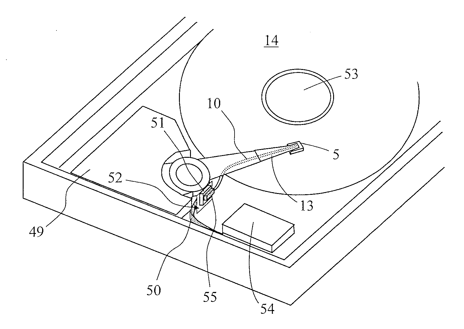
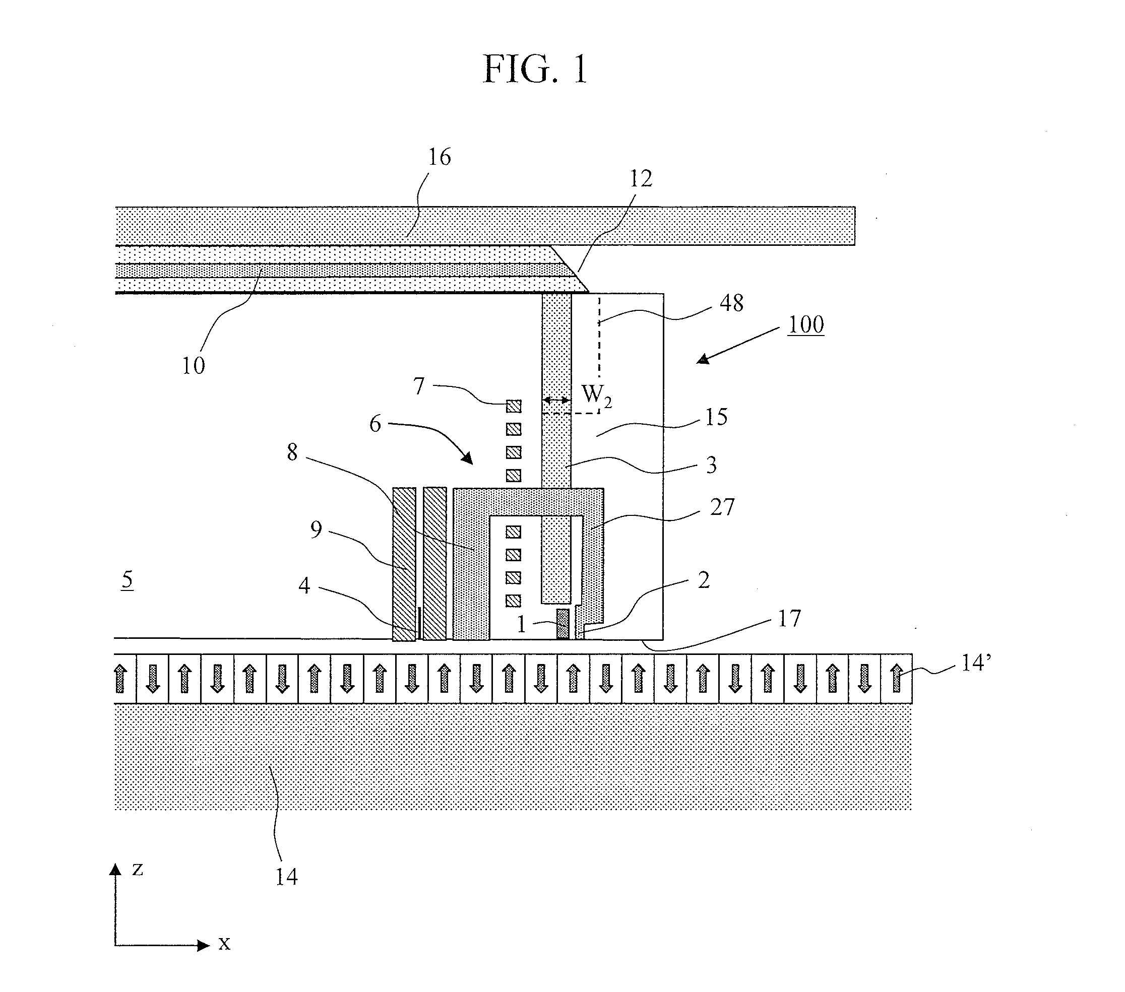
[0070]FIG. 1 shows a configuration example of a thermally assisted magnetic head 100 according to the present invention.

[0071]A semiconductor laser having a wavelength of 780 to 980 nm is used as a light source, and is installed near the base of a suspension (see reference numeral 55 in FIG. 39). A polymer waveguide 10 is used to transmit light from the light source to a slider 5. The polymer waveguide 10 is disposed on a flexure 16 of the suspension. A 45-degree mirror 12 is formed on an end face of the polymer waveguide 10 so that light emitted from the polymer waveguide 10 is emitted in a direction perpendicular to the upper surface of the slider 5. Although the polymer waveguide 10 is used as a waveguide for transmitting light from the light source to the slider 5 in this embodiment, any other waveguide, such as a quartz fiber or a plastic fiber, ...


PUM

PropertyMeasurementUnit
spread angleaaaaaaaaaa

Abstract

The present invention suppresses temperature rise of an optical near-field generator while increasing optical near-field intensity in a thermally assisted magnetic recording head using a conductive scatterer as the optical near-field generator. The present invention uses a conductive scatterer having a cross-sectional shape in which its width is gradually reduced toward an apex where an optical near-field is generated, and also has a shape in which its width is reduced gradually or in a stepwise fashion toward the apex where the optical near-field is generated in a traveling direction of incident light.

Description

CLAIM OF PRIORITY[0001]The present application claims priority from Japanese patent application JP 2009-245412 filed on Oct. 26, 2009, the content of which is hereby incorporated by reference into this application.BACKGROUND OF THE INVENTION[0002]1. Field of the Invention[0003]The present invention relates to an optical near-field generating device, a magnetic recording head including an optical near-field generating unit, and a magnetic recording device using the same.[0004]2. Description of the Related Art[0005]A thermally assisted recording method has recently been proposed as a recording method for achieving a recording density of 1 Tb / in2 or higher (H. Saga, H. Nemoto, H. Sukeda, and M. Takahashi, Jpn. J. Appl. Phys., 38, Part 1, 1839 (1999)). With a recording density of 1 Tb / in2 or higher, conventional magnetic recording devices have a problem that thermal fluctuations destroy recorded information. The prevention of this requires enhancement of coercivity of a magnetic recordi...

Claims


Application Information

Patent Timeline
Patent Type & Authority Applications(United States)
IPC IPC(8): G11B11/00
CPCG11B5/3116G11B5/314G11B2005/0021G11B2005/0005G11B5/6088
Inventor MATSUMOTO, TAKUYA
Owner HITACHI LTD
Why Eureka
Try Eureka