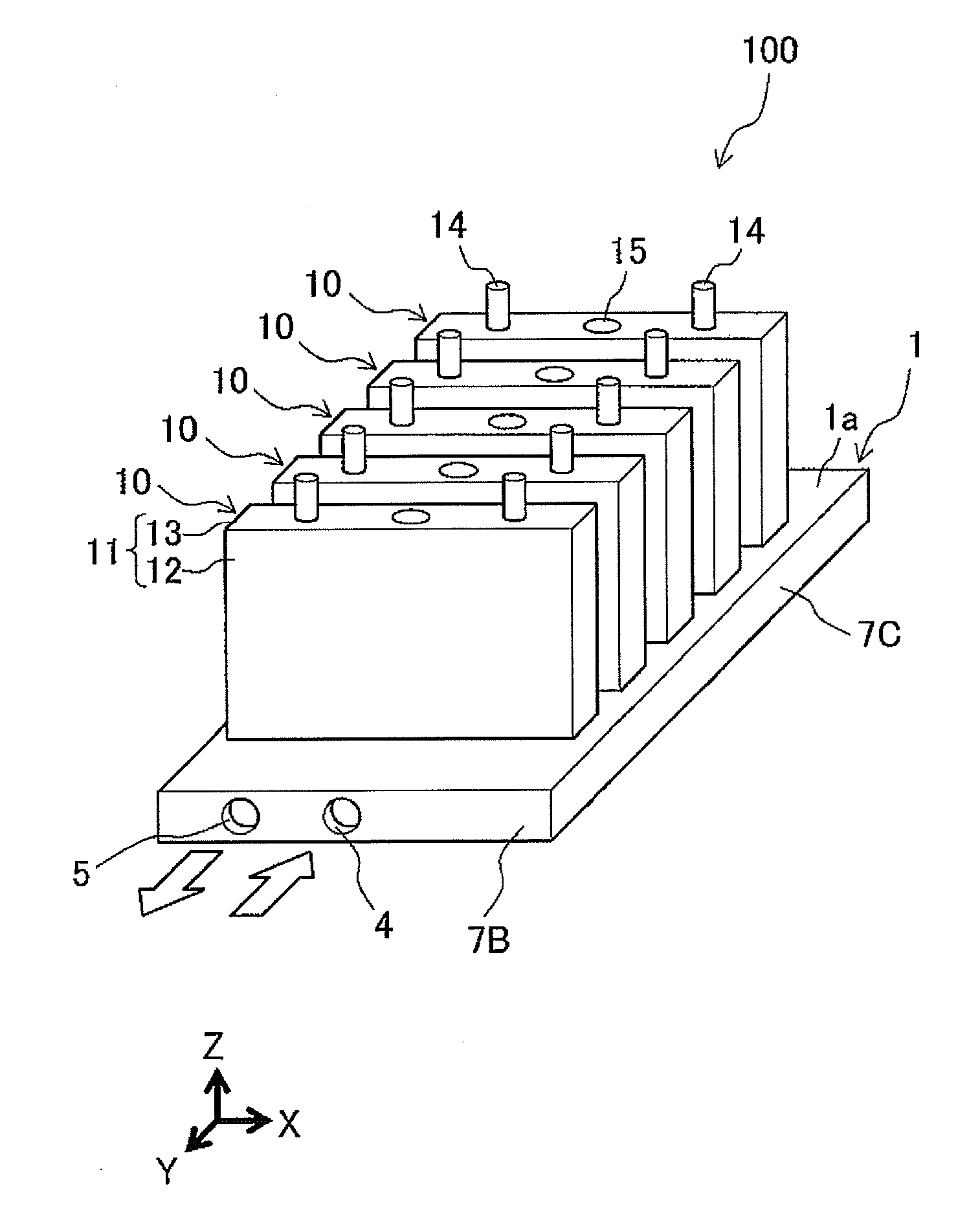
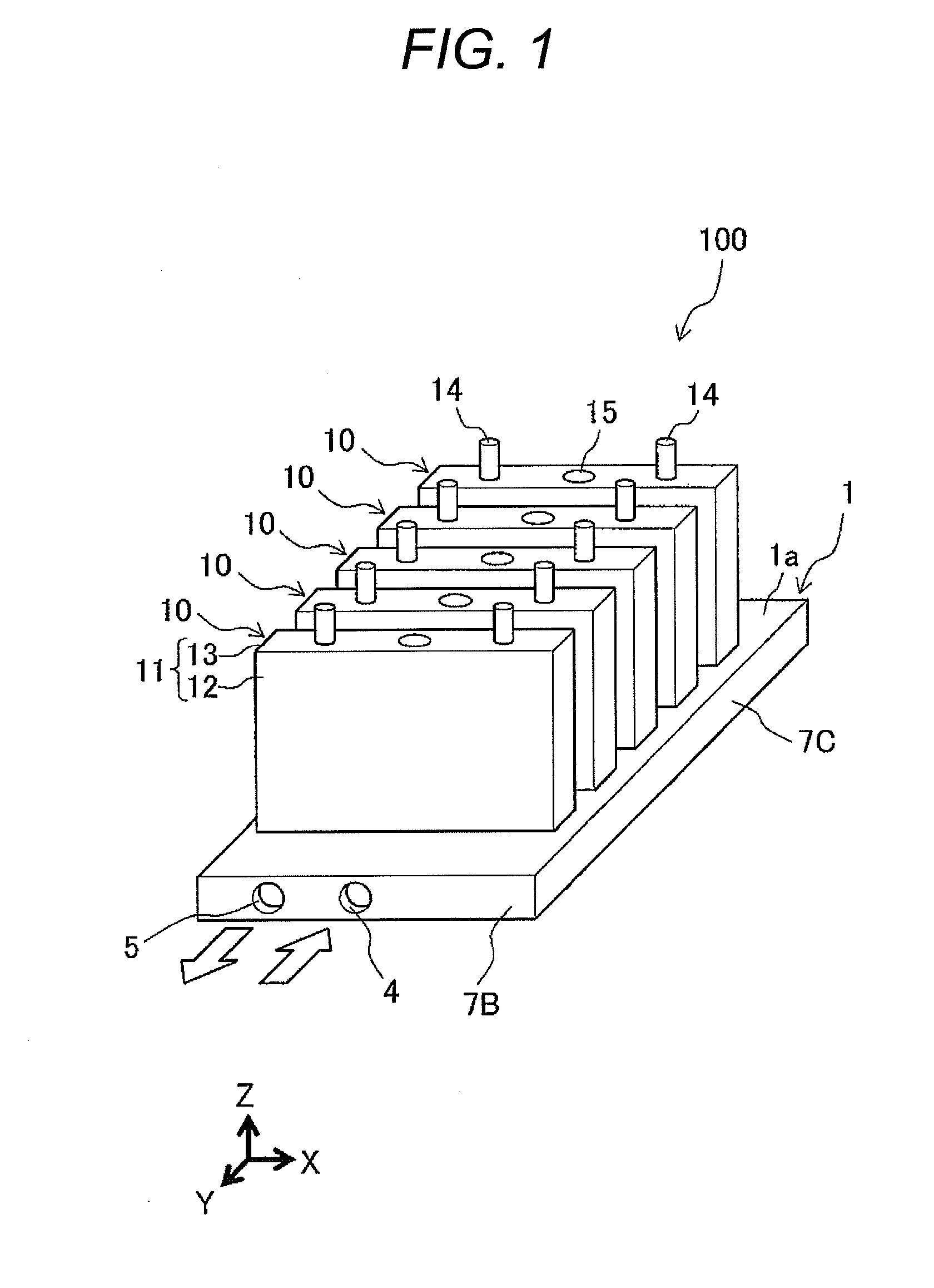
Battery module

a battery module and battery technology, applied in the field of batteries, can solve the problems of large cell temperature rise, large cell heat value, etc., and achieve the effects of reducing cell life between cells, reducing the variation of recharging and discharging amounts, and reliable and compact structur

Active Publication Date: 2015-05-21
HITACHI VEHICLE ENERGY
View PDF2 Cites 42 Cited by
  • Summary
  • Abstract
  • Description
  • Claims
  • Application Information

AI Technical Summary

Benefits of technology

[0009]According to the invention, the first channel part and the second channel part extend along the arrangement direction with the first partition part interposed therebetween, the one end of the first channel part of the arrangement direction and the one end of the second channel part of the arrangement direction are in communication with each other through the first communication part, and the flowing direction of coolant in the first channel part and the second channel part is turned. A direction of coolant flowing through the first channel part and a direction of coolant flowing through the second channel part are made opposite from each other, heat can be exchanged between the coolant flowing through the first channel part and coolant flowing through the second channel part through the first partition part, and this heat exchange can be carried out in the arrangement direction of the first channel part and the second channel part.
[0010]Therefore, when coolant flows from the first channel part to the second channel part for example, temperature of coolant in the second channel part located downstream of the first channel part located upstream becomes higher. However, since the first channel part and the second channel part extend in the arrangement direction with the first partition part interposed therebetween, an upstream portion of the first channel part having low temperature coolant and a downstream portion of the second channel part having high temperature coolant can be opposed to each other, and temperature rise of coolant flowing through the downstream portion of the second channel part can be made small by heat exchange carried out through the first partition part.
[0011]Therefore, the temperature distribution of the plate surface of the cooling plate can be adjusted to uniform temperatures of the plurality of cells arranged on the plate surface. Hence, it is possible to provide a reliable and compact battery module in which temperature rise of the cells caused by recharging and discharging operations of the cells is reduced and made further uniform, and variation in recharging and discharging amounts and cell lives between the cells is reduced. Objects, configurations and effects other than those described above will become apparent in the following description of embodiment.

Problems solved by technology

Generally, charge-and-discharge current of a battery module is large, heat values of the cells also become large and as a result, temperature of the cell itself also largely rises.

Method used


Image

  • Battery module
  • Battery module
  • Battery module

Examples


example 1

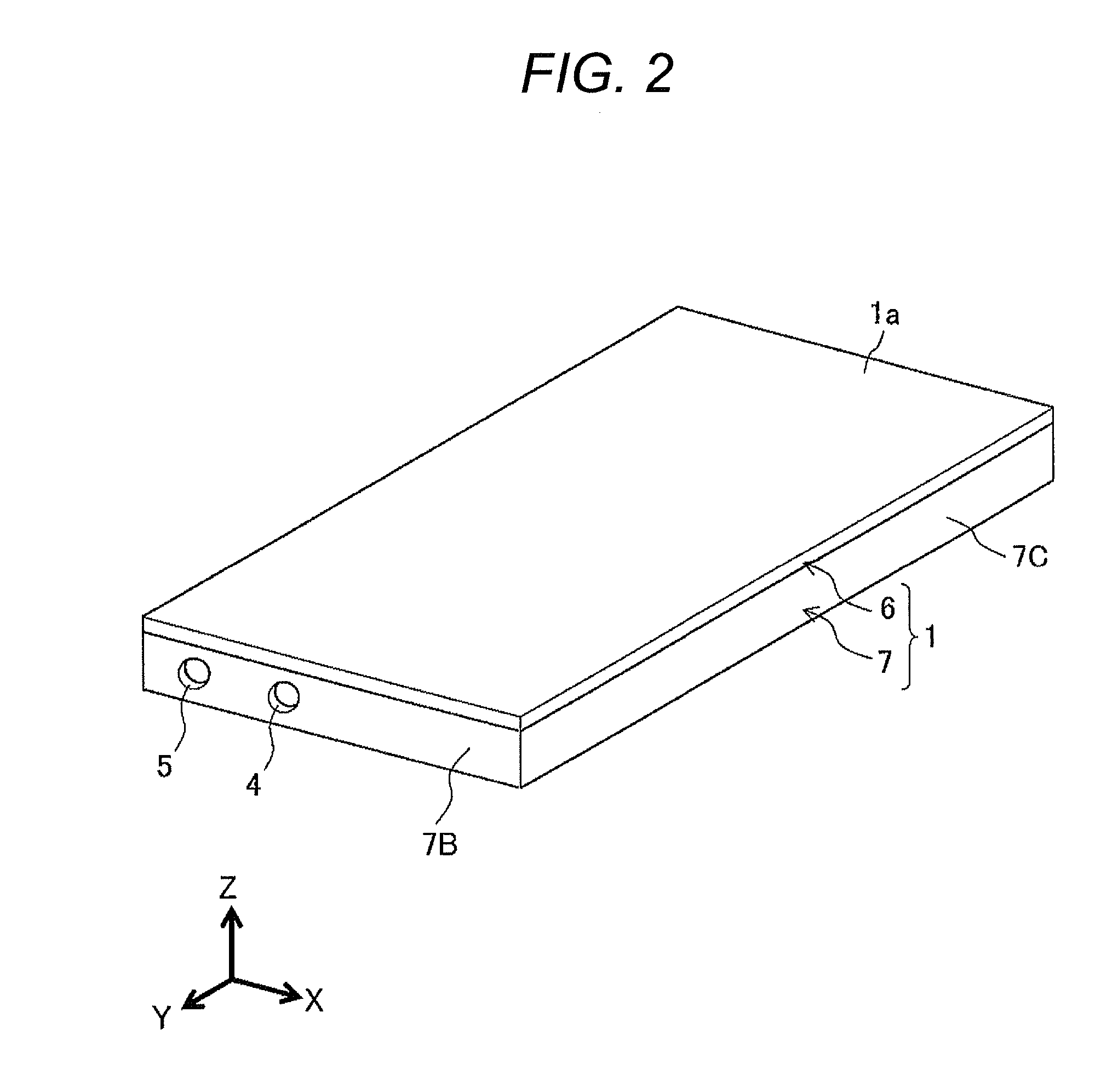
[0038]FIG. 4 is a sectional view of a cooling plate according to Example 1, and is a convenient diagram showing a flow of coolant.

[0039]As shown in FIG. 4, coolant flows into the channel part 2 of the cooling plate 1 from the coolant entrance 4, and straightly moves through the first channel part 2A having a channel width W1 toward one side of the arrangement direction. The coolant is deviated in the first communication part 2B having a channel width W2, a flowing direction is turned, and the coolant straightly moves through the second channel part 2C having a channel width W3 toward the other side of the arrangement direction. Then, the coolant is deviated in the second communication part 2D having a channel width W4, the flowing direction is turned, the coolant straightly moves through the third channel part 2E having a channel width W5 toward the one side of the arrangement direction, the coolant is deviated in the third communication part 2F having a channel width W6, the flowin...

example 2

[0052]FIG. 5 is a sectional view of a cooling plate according to Example 2, and is a convenient diagram showing a flow of coolant.

[0053]Example 2 is characterized in that narrow portions having narrow channel cross sections are provided at intermediate portions of a channel of a channel part 2, speed of a flow of coolant is increased at the narrow portion, and after the coolant passes through the narrow portion, speed thereof is reduced, and the speed of coolant flowing through the channel part 2 is changed such that the speed is repeatedly increased and reduced.

[0054]A basic configuration of Example 2 is similar to that of Example 1. However, as compared with the configuration of Example 1, the channel widths W2, W4 and W6 of the first communication part 2B, the second communication part 2D and the third communication part 2F are smaller than the channel widths W1, W3, W5 and W7 of the first channel part 2A, the second channel part 2C, the third channel part 2E and the fourth chann...

example 3

[0059]FIG. 6 is a sectional view of a cooling plate according to Example 3, and is a convenient diagram showing a flow of coolant.

[0060]Example 3 is characterized in that in addition to the configuration of above-described Example 2, a channel cross-sectional area of the channel part 2 on the upstream side is made narrower than that on the downstream side so that flowing speed on the downstream side of the channel part 2 is increased.

[0061]A basic configuration of Example 3 is similar to that of Example 2. However, as compared with the configuration of Example 2, the channel width W1 of the first channel part 2A is larger than the channel width W3 of the second channel part 2C and the channel width W5 of the third channel part 2E, and the channel width W7 of the fourth channel part 2G is smaller than the channel width W3 of the second channel part 2C and the channel width W5 of the third channel part 2E.

[0062]According to Example 3, flowing speed in the fourth channel part 2G on the...


PUM

PropertyMeasurementUnit
thicknessesaaaaaaaaaa
lengthaaaaaaaaaa

Abstract

A battery module of includes a plurality of cells, a cooling plate, and a channel part formed in the cooling plate. The channel part includes a first channel part extending in an arrangement direction of the plurality of cells, a second channel part extending in parallel to the first channel part along the arrangement direction with a first partition part interposed between the first channel part and the second channel part, and a first communication part which brings one end of the first channel part of the arrangement direction and one end of the second channel part of the arrangement direction into communication with each other, and which turns a flowing direction of coolant in the first channel part and the second channel part.

Description

TECHNICAL FIELD[0001]The present invention relates to a battery module configured by connecting a plurality of rechargeable / dischargeable cells to each other.BACKGROUND ART[0002]A battery module provided in a hybrid vehicle, an electric vehicle and the like as a power source device is configured by connecting, to each other, a plurality of cells such as a lithium-ion rechargeable battery, a nickel-hydride rechargeable battery and a nickel-cadmium rechargeable battery for example. Generally, charge-and-discharge current of a battery module is large, heat values of the cells also become large and as a result, temperature of the cell itself also largely rises. It is preferable that temperature rise of a cell is suppressed as small as possible in terms of battery life, and it is necessary to swiftly cool the battery.[0003]One method of swiftly cooling the plurality of cells, there is using liquid coolant. For example, there is known a method that a plurality of cells are coupled to each...

Claims


Application Information

Patent Timeline
Patent Type & Authority Applications(United States)
IPC IPC(8): H01M10/625H01M10/613H01M10/656H01M50/209H01M50/224H01M50/271
CPCH01M10/5016H01M2220/20H01M10/5004H01M10/5061H01M50/271H01M50/224H01M50/209H01M10/625H01M10/647H01M10/613H01M10/656H01M10/6556Y02E60/10H01M10/617
Inventor HARADA, SUSUMUSUGA, ATSUOSEKINE, ATSUSHI
Owner HITACHI VEHICLE ENERGY
Why Eureka
Try Eureka