Vehicle radar apparatus having variable output power controlled based on speed of vehicle
A radar device, a technology of output power, applied in the direction of measurement device, reflection/re-radiation of radio waves, utilization of re-radiation, etc., can solve problems such as inability to detect obstacles, and achieve the effect of improving energy efficiency
- Summary
- Abstract
- Description
- Claims
- Application Information
AI Technical Summary
Problems solved by technology
Method used
Image
Examples
no. 1 example
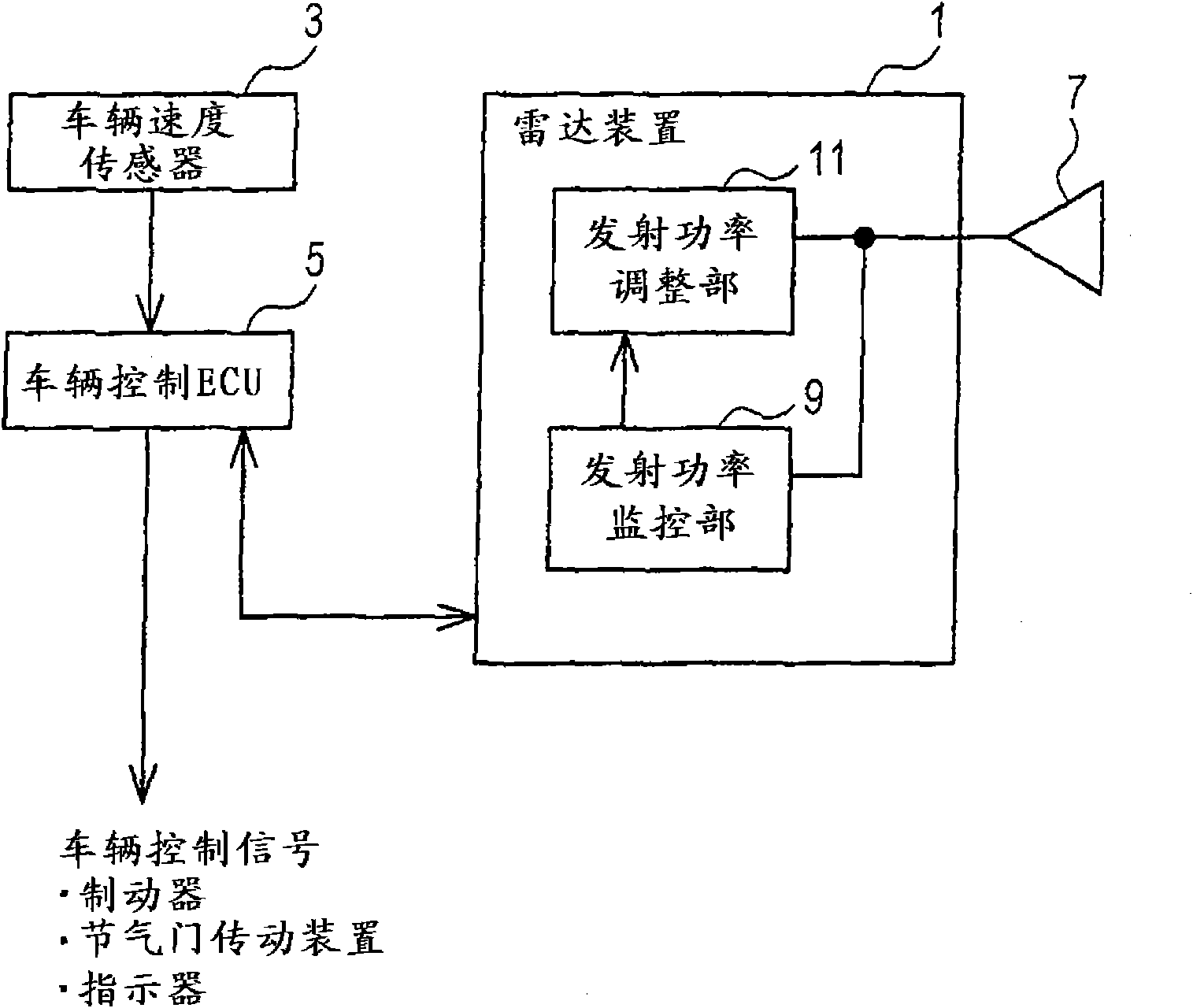
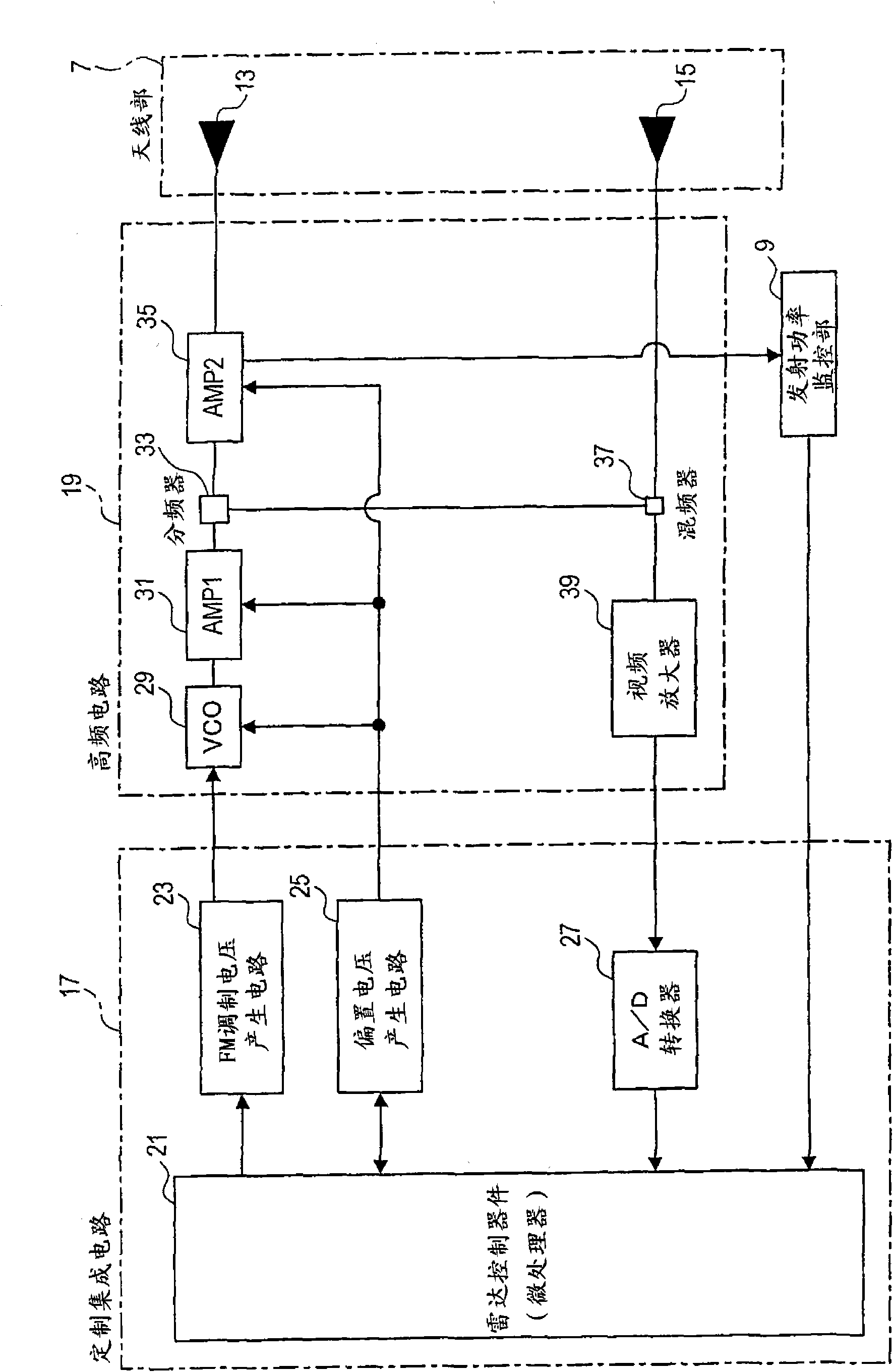
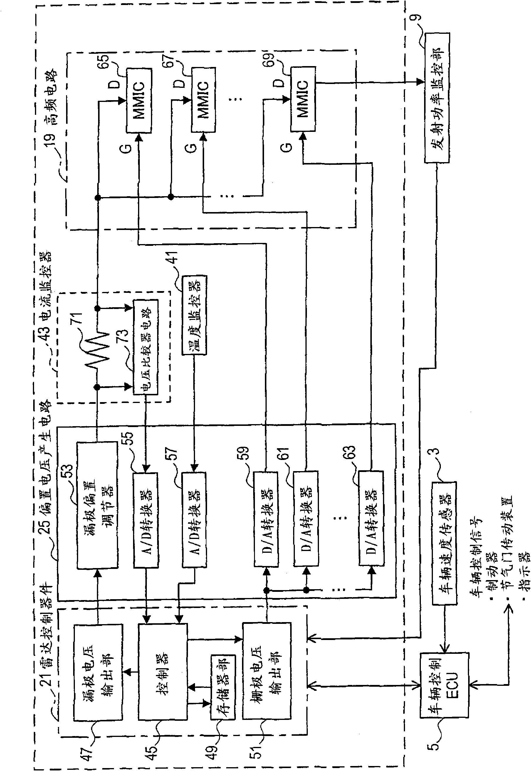
[0044] Refer to attached Figures 1 to 8 , the first embodiment according to the present invention will be described below.
[0045] The radar device according to the present invention controls the transmission power of the radar device in response to the speed of the vehicle. In addition, the radar device is configured to have a function of monitoring whether the transmission power of the radar device is within a target range.
[0046] a) First, the general configuration of a vehicle system including the radar apparatus of the first embodiment is described as follows.
[0047] like figure 1 As shown, the vehicle is equipped with a radar device 1, a vehicle speed sensor 3, and a vehicle control unit 5, ie, a vehicle control electronic control unit (ECU). The radar device 1 detects the traveling speed of the preceding vehicle traveling ahead of the host vehicle, the distance from the preceding vehicle, or the like. A vehicle speed sensor 3 detects the running speed of the h...
no. 2 example
[0106] refer to Figures 9 to 10A - 10C, The second embodiment will be described below. However, explanations whose contents are similar to those of the first embodiment are omitted. In the second embodiment, the control process of the radar transmit power is different from that in the first embodiment. Such as Figure 9 As shown in , the main part of the radar apparatus according to the second embodiment is shown. The radar control device 101 includes a controller 103 and a memory section 105 . The FM modulation voltage generation circuit 107 connected to the radar control device 101 outputs a triangular wave, which is sent to the VCO 109 of the MMIC.
[0107] The specific procedures for adjusting the radar transmission power are described as three types of procedures a) to c) as follows. Here is described a process in which the transmission power when the vehicle is in the normal speed state is switched to the transmission power when the vehicle is in the low speed stat...
no. 3 example
[0119] refer to Figures 11 to 13 , the third embodiment will be described below. However, explanations whose contents are similar to those of the first embodiment are omitted. In a third embodiment, the radar transmit power of the radar arrangement is monitored and controlled in response to vehicle speed.
[0120] a) First, configurations for monitoring transmission power and controlling transmission power, which are features of the present invention, are described as follows. Such as Figure 11 As shown, similarly to the first embodiment, the high frequency circuit 111 includes a VCO 113, an amplifier (AMP 1) 115, a frequency divider 117, an amplifier (AMP 2) 119, a transmitting antenna 121, and the like.
[0121] Such as Figure 11 As shown, the transmission power monitoring unit 123 includes a detection diode 125, a differential amplifier 126 and the like. In the emission monitoring unit 123 , the emission power (emission voltage) from the amplifier 119 of the high-fr...
PUM
 Abstract
Description
Claims
Application Information
 - R&D
- Intellectual Property
- Life Sciences
- Materials
- Tech Scout
- Unparalleled Data Quality
- Higher Quality Content
- 60% Fewer Hallucinations
Browse by: Latest US Patents, China's latest patents, Technical Efficacy Thesaurus, Application Domain, Technology Topic, Popular Technical Reports.
© 2025 PatSnap. All rights reserved.Legal|Privacy policy|Modern Slavery Act Transparency Statement|Sitemap|About US| Contact US: help@patsnap.com


