Tubular actuator for driving a roller shutter

A technology of actuators and tubes, applied in the direction of windows/doors, door/window protection devices, shading screens, etc., which can solve the problems of interchangeability, fragility, reinforcement, etc.

Inactive Publication Date: 2010-11-10
SOMFY SAS
View PDF9 Cites 10 Cited by
  • Summary
  • Abstract
  • Description
  • Claims
  • Application Information

AI Technical Summary

Problems solved by technology

However, in view of the mentioned force limitations, apart from strengthening the action of the fixing means not described in this patent document, this interchangeability seems to be particularly weak

Method used


Image

  • Tubular actuator for driving a roller shutter
  • Tubular actuator for driving a roller shutter
  • Tubular actuator for driving a roller shutter

Examples


Embodiment Construction

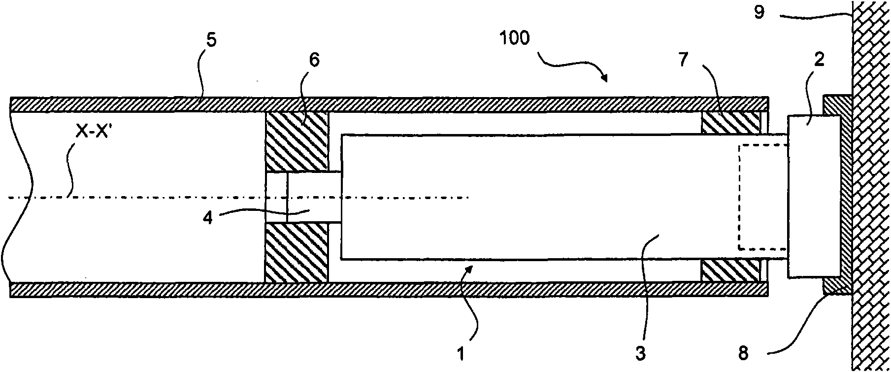
[0035] figure 1 A device 100 comprising a tubular actuator 1 is shown. Said tubular actuator comprises a fixed point part 2, a tubular body 3 and an output shaft body 4 which is movable in rotation according to the axis XX' of the tubular body of the actuator. The output shaft body is connected to a winding tube 5 in which the actuator is engaged by means of a drive wheel 6 . A bearing 7 allows the guidance of the winding tube in rotation on the tube of the actuator. A fixing fitting 8 connects the fixing point part to a frame 9 . A windable element, not shown, is fastened via one end to the winding tube. Fastening fittings are fixed to a frame, such as the structure of a building. It is preferably fixed directly on the frame. Furthermore, a fixed fitting is used to receive the fixed point part of the actuator. It has, for example, structural features for this purpose. The fastening fitting thus allows the indirect fastening of the fastening point part to the frame.

...


PUM


Abstract

The present invention relates to a tubular actuator (1) for driving a windable element in a building, comprising: in a tube (3) having a longitudinal axis (X-X'), a reduction gear and an output shaft (4) at a first end of the tube and a fixed-point member (2) in two portions at a second end of the tube, the fixed-point member comprising a first portion (20; 20') at least partially outside the tube and a second portion (40; 40') assembled in the tube, wherein the first portion comprises at least one torque and weight-bearing axial extension, this torque and weight-bearing axial extension being capable of being inserted into at least one recess of the second portion and being locked in translation along the longitudinal axis relative to the tube of the actuator by a first locking means.

Description

technical field [0001] The invention relates to a tubular actuator for driving a rollable element in a building, such as a blind, a sun or anti-camera curtain, a rolling shutter. The actuator is inserted in a winding tube on which the windable element is wound. Background technique [0002] The tubular actuator includes an end piece that is attached to a portion of a frame that supports a portion of the weight of the actuator, winding barrel and windable element, typically the half the weight and fully support the moment of the actuator. This end piece is often referred to as the "fixed point piece" or even the "head" of the actuator. [0003] The actuator head is thus dimensioned to satisfy these mechanical constraints, while also minimizing its volume in the axial direction: practically, windable elements cannot be wound on the head, and if windable The element is not arranged in a specific housing of the frame, and the width of the head thus likewise reduces the width ...

Claims


Application Information

Patent Timeline
Patent Type & Authority Applications(China)
IPC IPC(8): E06B9/72
CPCE06B9/50E06B9/72E06B9/174E06B9/171E06B9/42
Inventor B·迪科尔内D·马格里
Owner SOMFY SAS
Why Eureka
Try Eureka