
Tamper-proof lock

An anti-prying and anti-prying hole technology is applied in the field of anti-prying locks, which can solve the problem of inability to effectively protect items, and achieve the effect of avoiding illegal unlocking, protecting items, and preventing items from being stolen.

Inactive Publication Date: 2012-11-14
VANCE LOCK INDAL
View PDF0 Cites 0 Cited by
  • Summary
  • Abstract
  • Description
  • Claims
  • Application Information

AI Technical Summary

Problems solved by technology

As a result, the lock 70 cannot effectively achieve the effect of protecting articles and preventing articles from being stolen, so there is indeed room for further improvement.

Method used


Image

  • Tamper-proof lock
  • Tamper-proof lock
  • Tamper-proof lock

Examples


Embodiment Construction

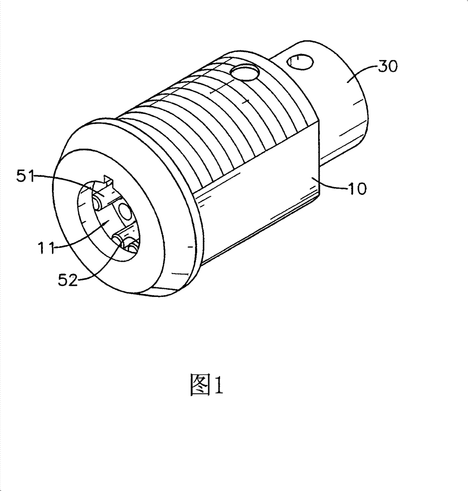
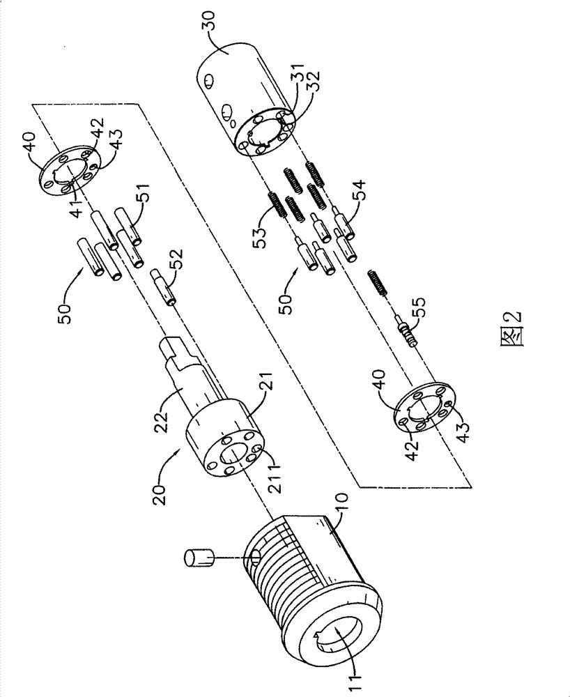
[0028] see figure 1 as well as figure 2 As shown, the tamper-resistant lock of the present invention includes a hollow lock case 10, an upper bead seat 20, a lower bead seat 30, two locking plates 40 and a positioning assembly 50, wherein:

[0029] An accommodating space 11 is formed axially through the inside of the lock case 10, so that the two ends of the lock case 10 are respectively a front end and a rear end;

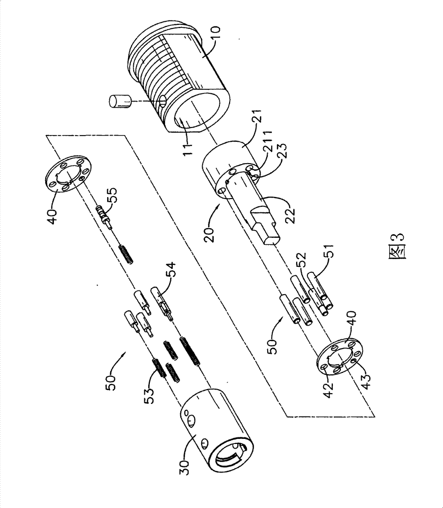
[0030] Cooperate see image 3 as well as Figure 4 As shown, the upper bead seat 20 is passed through the accommodating space 11 of the lock housing 10, and it includes a crown portion 21, a sleeve portion 22 and at least a pair of positioning portions 23, and the crown portion 21 corresponds to On the front end of the lock housing 10, a plurality of through holes 211 are formed around the periphery at intervals and axially penetrated therethrough. The sleeve portion 22 extends axially from an inner end surface of the crown portion 21, which corresponds to I...


PUM


Abstract

The invention discloses a tamper-proof lock consisting of an upper ball seat, a lower ball seat and a locating assembly located between the upper ball seat and the lower ball seat, wherein the locating assembly comprises at least one clamping plate, at least one tamper-proof locating pin and at least one tamper-proof bolt, and the tamper-proof bolt is provided with at least one ring slot in a concave-convex manner. When some one uses an unlocking tool to illegally unlock, the clamping plate may be embedded in the ring slot of a lock rod, thus the illegal unlocking operation can not continue; only when a right key is used for unlocking, each tamper-proof locating pin and the tamper-proof bolt can be pushed for a certain distance in order to further unlock, thereby preventing a man of intention, who uses the unlocking tool, from illegally unlocking, and the tamper-proof lock can effectively protect objects and prevent the objects from being stolen.

Description

technical field [0001] The invention relates to a lockset, in particular to an anti-picking lock which can be prevented from being opened by a lock tool. Background technique [0002] A lock is a device that can be used to protect personal items and maintain personal privacy. A specific key used with the lock can be inserted and turned to open the lock, so as to ensure the safety of items and prevent theft. Effect. [0003] see Figure 8 A prior art lock 70 is shown, which mainly includes a hollow lock case 71, an upper bead seat 72, a lower bead seat 73 and a positioning assembly 74; [0004] The upper bead seat 72 is passed through the lock shell 71, and it includes a crown 721 and a socket 722. The crown 721 corresponds to a front end of the lock shell 71, on which A plurality of through-holes 723 are formed around the periphery at intervals and axially penetrated. The sleeve portion 722 extends axially from one end of the crown portion 721 toward the other rear end of ...

Claims


Application Information

Patent Timeline
Patent Type & Authority Patents(China)
IPC IPC(8): E05B27/06E05B15/00
Inventor 林圣庭
Owner VANCE LOCK INDAL
Learn More