Drive device for passenger conveyer

A technology of passenger conveying equipment and driving devices, applied in escalators, transportation and packaging, etc., can solve problems such as rising costs and achieve superior maintainability

Active Publication Date: 2013-01-30
HITACHI LTD
View PDF1 Cites 0 Cited by
  • Summary
  • Abstract
  • Description
  • Claims
  • Application Information

AI Technical Summary

Problems solved by technology

[0008] However, in the above-mentioned prior art, since it is necessary to provide a dedicated rotation shaft for the rotation detection unit, not only will the cost increase, but also because the rotation detection unit and the rotation shaft of the speed reducer are staggered, there will be problems. Problems leading to device enlargement

Method used


Image

  • Drive device for passenger conveyer
  • Drive device for passenger conveyer
  • Drive device for passenger conveyer

Examples


Embodiment Construction

[0024] Hereinafter, embodiments of the driving device of the passenger conveying facility according to the present invention will be described with reference to the drawings.

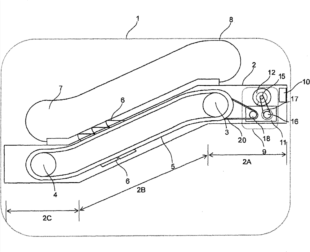
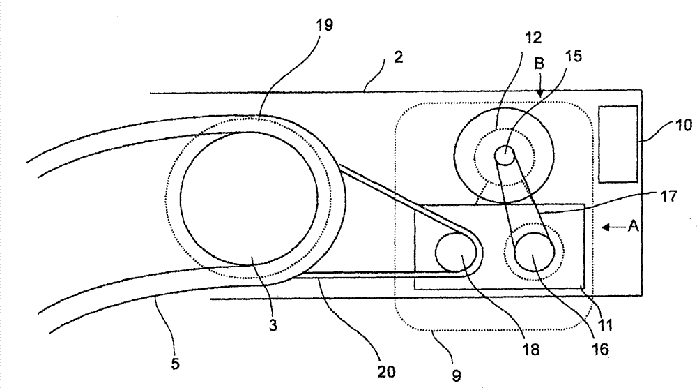
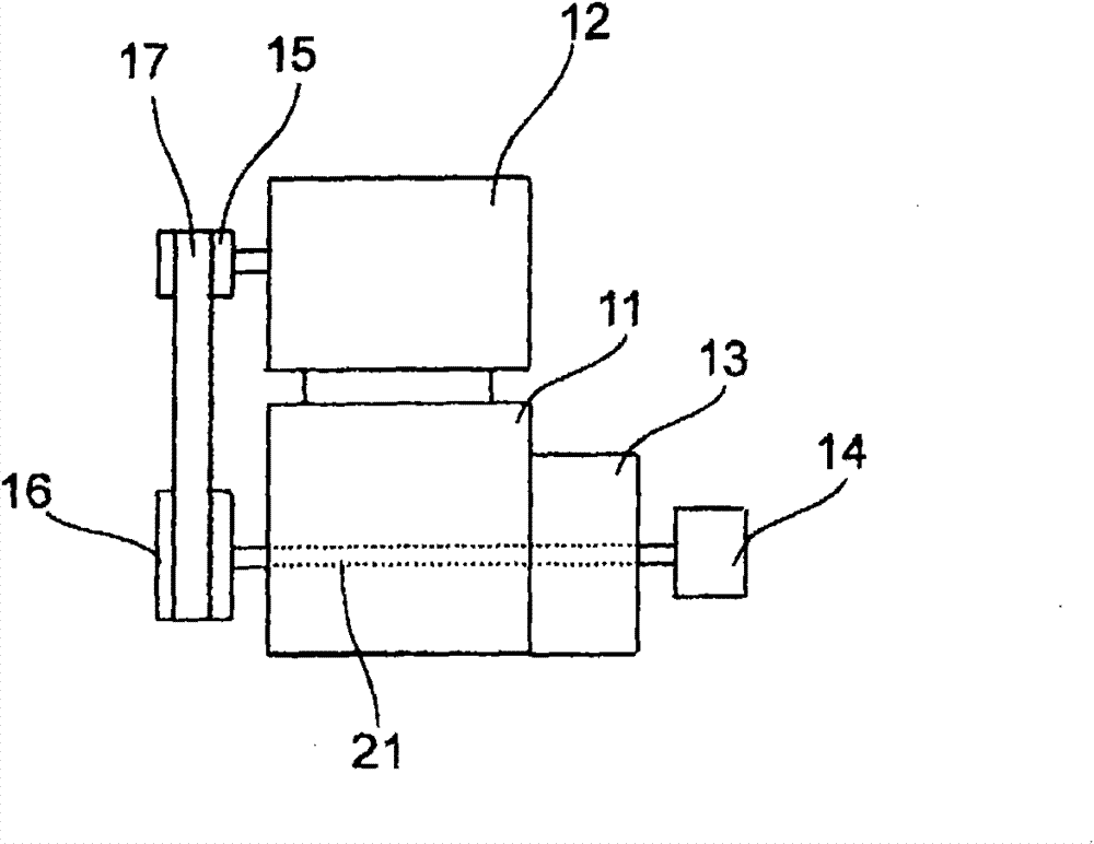
[0025] figure 1 It is a brief structural diagram of the overall appearance of the passenger conveying equipment to which the driving device of the present invention is applied, figure 2 It is an enlarged view of the main part of the passenger transport facility, image 3 From figure 2 The front view of the drive unit when viewed in the direction of A, Figure 4 From figure 2 A top view of the drive unit when viewed in direction B, Figure 5 It is a plan view of main parts showing one embodiment of the driving device of the passenger conveyor according to the present invention, Figure 6 From Figure 5 The main part front view when viewed from the C direction.

[0026] Such as figure 1 As shown, the passenger conveying equipment, such as an escalator 1, has: a frame body 2, which is arranged...


PUM


Abstract

The present invention provides a drive device for a passenger conveyor in which a rotation detection means is disposed coaxially with the rotating shaft of a speed reduction gear and which has superior maintainability. This drive device includes the speed reduction gear having an outer plate disposed on the outside of a braking body, the rotation detection means for detecting the rotational speed of the rotating shaft, and a restriction means which is formed of a bracket provided to the rotation detection means and pins one end of which is fixed to the outer plate and the other end of which is engaged with the bracket and which restricts the rotation detection means in the rotating direction. The inner diameter dimension of the outer plate is set larger than the outer diameter dimension of the rotation detection means. A groove one end of which is open is provided to the restriction means. The bracket and the pin are engaged by inserting the pin into the bracket. The engagement of the bracket and the pin is released by separating the outer plate from the braking body.

Description

technical field [0001] The present invention relates to a driving device for passenger transport equipment such as an escalator in which adjacent pedals produce a height difference and an electric passageway in which there is no height difference between adjacent pedals, and in particular relates to a rotation detection device for detecting the speed of the speed reducer. The drive of the unit's passenger conveyor. Background technique [0002] In general, a motor that applies a driving force and a speed reducer having a brake body that applies a braking force to a rotating shaft are provided in a passenger conveying device, and the rotation speed of the speed reducer is detected by a rotation detection unit for operation control. [0003] Figure 8 It is a schematic structural diagram showing the driving device of the conventional passenger conveying equipment. [0004] Such as Figure 8 As shown, the driving device of the passenger conveying equipment in the prior art has...

Claims


Application Information

Patent Timeline
Patent Type & Authority Patents(China)
IPC IPC(8): B66B23/02
Inventor 竹本启辅山下智典福田敏行五味雅志
Owner HITACHI LTD
Why Eureka
Try Eureka