
Locking and sealing electric connector

A technology of electrical connectors and connecting caps, which is applied in the direction of connection, parts and circuits of connection devices, etc. It can solve the problems of seal failure, seal failure of the end face of the plug shell and the rubber ring of the socket shell, etc., and achieve the corresponding mating accuracy , The effect of convenient locking operation

Active Publication Date: 2012-07-18
CHINA AVIATION OPTICAL-ELECTRICAL TECH CO LTD
View PDF0 Cites 1 Cited by
  • Summary
  • Abstract
  • Description
  • Claims
  • Application Information

AI Technical Summary

Problems solved by technology

The commonly used structure in the above-mentioned locking and sealing connector has no problem in normal use, but there is a defect of sealing failure. This is because, when the plug and the socket are connected in place, the connecting cap of the plug is blocked by the staple of the socket and It cannot move axially, which means it is fixedly connected with the socket, but the plug shell is still elastically stretchable with the connecting cap in the axial direction. If a force is applied to the plug shell in the opposite direction At this time, the plug housing can continue to compress the spring (spring washer or corrugated spring) and move backward, and the end face of the plug housing will no longer press against the rubber ring to deform, resulting in a gap between the end face of the plug housing and the rubber ring of the socket housing. seal failure
In actual use, due to the fixed connection between the plug housing and the cable, it is easy to pull the cable, so the existing above-mentioned locking and sealing electrical connector has the technical problem of easy sealing failure

Method used


Image

  • Locking and sealing electric connector
  • Locking and sealing electric connector
  • Locking and sealing electric connector

Examples


Embodiment Construction

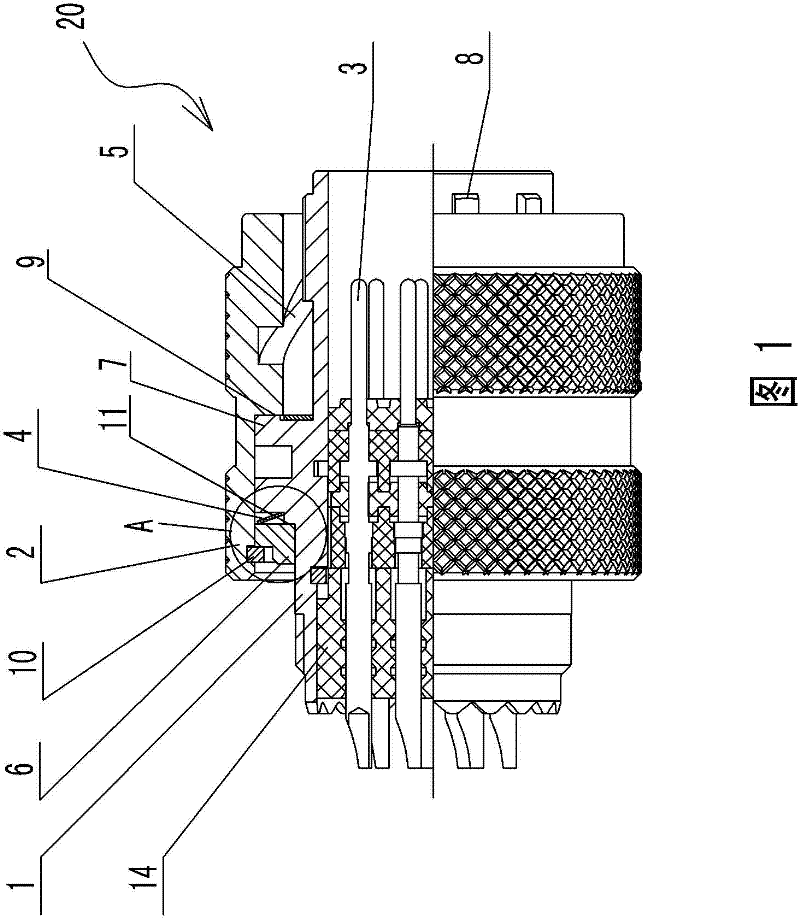
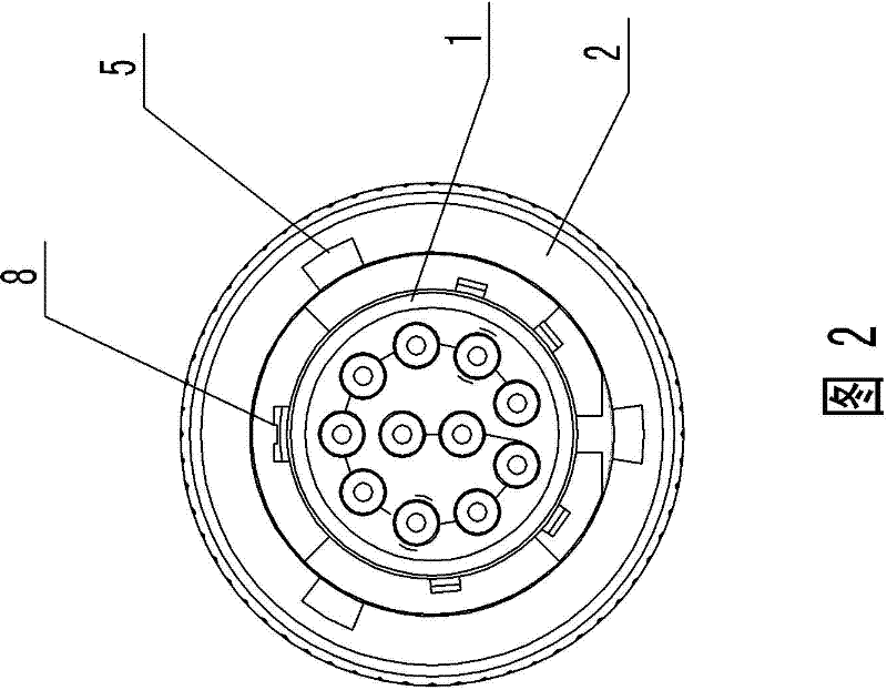
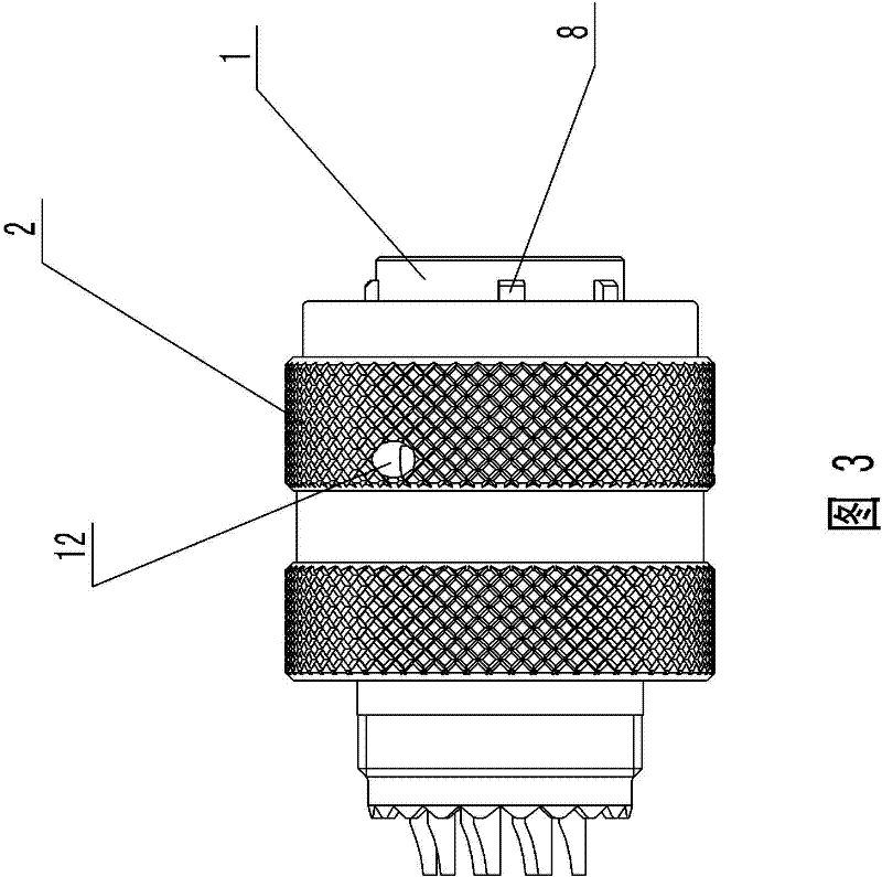
[0025] Such as Figure 1 to Figure 5 As shown, the plug 20 of the present invention has a cylindrical shape as a whole, and the front and rear ends are respectively a plug-in terminal and a terminal. A plug insulator 14 is installed in the housing 1, and a plug contact 3 protruding from the front end of the plug insulator 14 is installed in the plug insulator 14. A plurality of guide keys 8 are extended, and the inner wall of the connecting cap 2 is provided with three curved grooves 5 extending backward from the outer end of the connecting cap. Staple holes 12 for snapping in of the staples on the socket housing.

[0026] A rigid thrust structure is provided between the outer peripheral surface of the plug housing 1 and the inner wall of the connecting cap 2 behind the staple hole 12, and the rigid thrust structure is axially rigid and limited. The rigid thrust structure of the connection cap on the inner wall of the connection cap 2 and the rigid thrust structure of the pl...


PUM


Abstract

The invention discloses a locking and sealing electric connector. The electric connector comprises a plug and a socket, wherein the plug comprises a plug shell and a connecting cap sleeved on the periphery of the plug shell rotatably; the socket comprises a socket shell of which the outer wall is provided with a staple bolt; a sealing ring which is used for matching the end face of the plug shellin a sealing way is arranged in the socket; one end, back to the plug incoming direction of the plug, of the sealing ring is provided with an annular end face which is matched with the socket in a resisting way; the annular end face is provided with an annular groove which is distributed in a ring shape; and a rigid thrust structure in rigid thrust limit matching in the axial direction is arranged between the outer peripheral surface of the plug shell and the inner wall, positioned behind the staple bolt, of the connecting cap. In the electric connector, by changing the structure of the sealing ring structure, a locking connecting cap and the plug shell cannot move relative to the axial direction, so that the problem of seal failure is stopped and locking design and locking operation are not affected at the same time.

Description

technical field [0001] The present invention relates to electrical connectors. Background technique [0002] like Figure 11 As shown, the existing type of locking and sealing electrical connector adopts a three-curved groove buckle connection structure, which requires that after the contacts in the plug and the corresponding contacts in the socket are connected in place, at the same time ensure that the plug shell and the socket shell body locking and sealing, which requires the end face of the plug housing 41 to compress the sealing ring 50 in the socket while the staple hole on the inner surface of the connecting cap 42 carried by the plug housing 41 can be displaced to the socket housing The position of the staple on the outer wall enables the staple to slide into the staple hole just along the groove line of the three-curved groove 44 . In order to facilitate the above-mentioned fitting in place and compression of the sealing ring, it is a common practice in the prior...

Claims


Application Information

Patent Timeline
Patent Type & Authority Patents(China)
IPC IPC(8): H01R13/52H01R13/623
Inventor 王卫李森
Owner CHINA AVIATION OPTICAL-ELECTRICAL TECH CO LTD
Learn More