
Solder strip drawing and releasing mechanism

A technology of welding strip and clamping jaw, applied in the field of welding strip pulling and releasing mechanism

Inactive Publication Date: 2010-12-08
天津必利优科技发展有限公司
View PDF5 Cites 11 Cited by
  • Summary
  • Abstract
  • Description
  • Claims
  • Application Information

AI Technical Summary

Problems solved by technology

The position of the ribbon used for welding on the battery determines the final welding effect and has an important impact on the efficiency of the battery after welding. This requires a ribbon that can automatically place the ribbon according to the position of the battery. Placement mechanism to ensure the subsequent welding effect, currently there is no such mechanism for pulling and releasing the welding ribbon

Method used


Image

  • Solder strip drawing and releasing mechanism
  • Solder strip drawing and releasing mechanism
  • Solder strip drawing and releasing mechanism

Examples


Embodiment approach

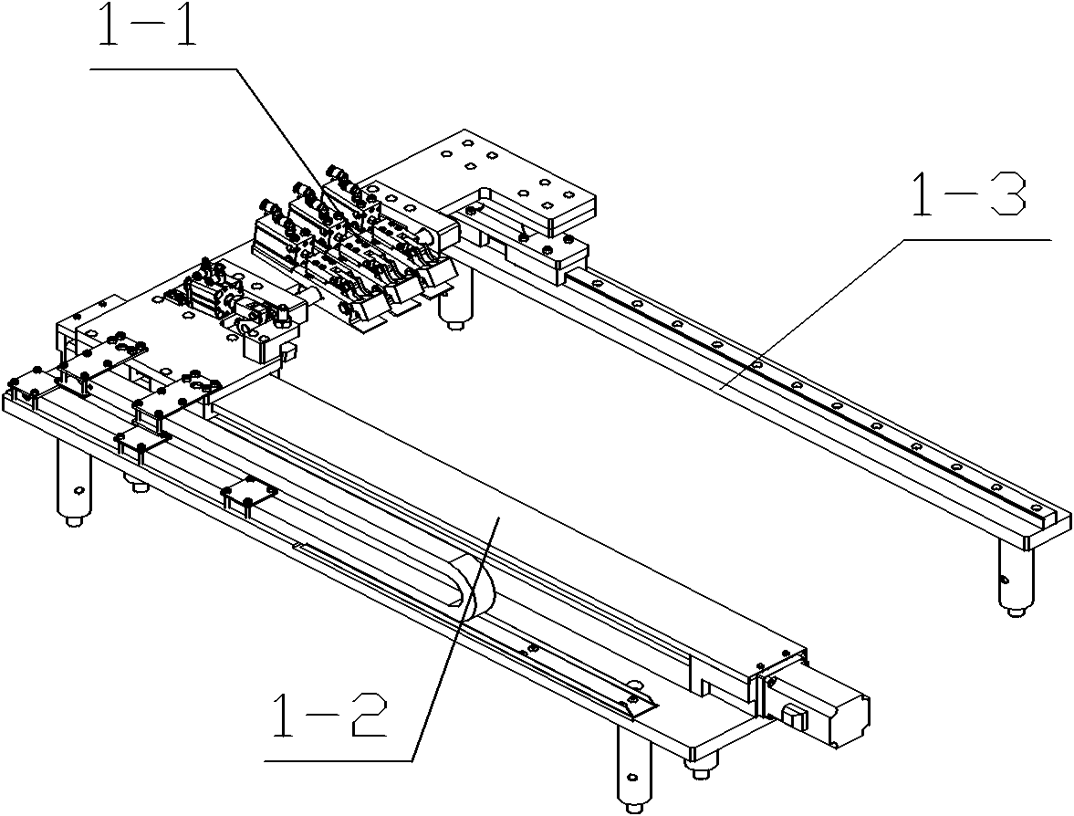
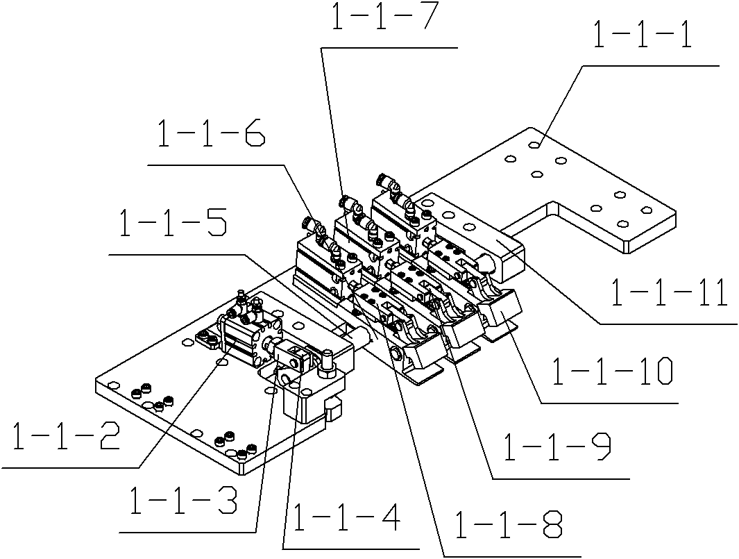
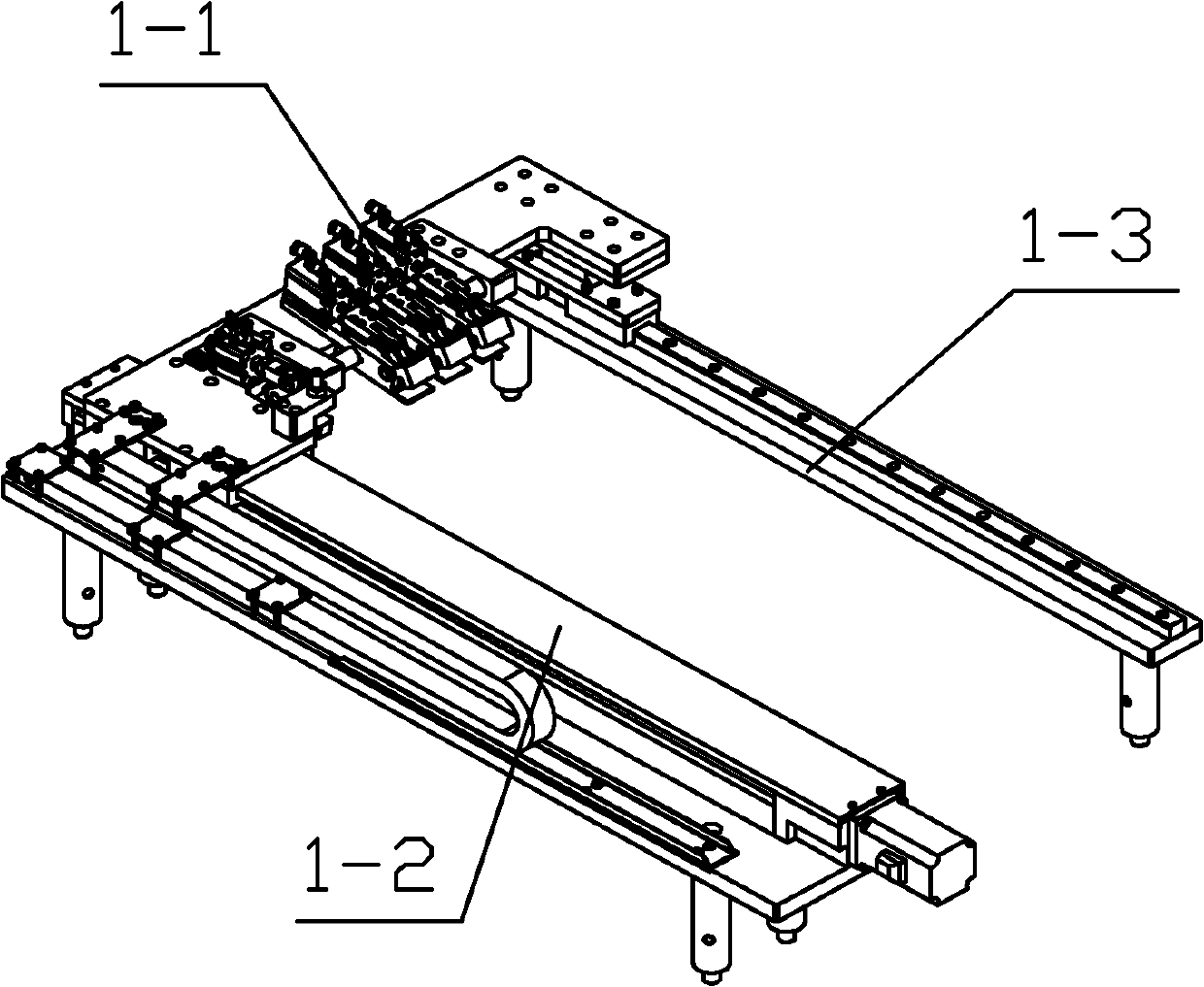
[0012] The motor in the ribbon pulling and releasing mechanism drives the air claw assembly 1-1 to move to clamp the ribbon; according to the set moving distance, the air claw assembly 1-1 stops moving after reaching a fixed length, and waits for the cutting mechanism to cut off the ribbon ; In the ribbon pulling and releasing mechanism, the motor drives the air claw assembly 1-1 to move the cut ribbon to the placement position, and the rotating cylinder 1-1-2 drives the rotating shaft 1-1-5 to rotate, so that the jaws support 1- The gripper fingers of 1-6 move down, and then the gripper fingers move the cylinder 1-1-7 to drive the gripper fingers 1-1-10 to move, so that the gripper fingers 1-1-10 will loosen the welding ribbon Place it on the object to be welded. The rotary moving cylinder 1-1-2 drives the rotating shaft 1-1-5 to rotate, so that the jaw fingers of the jaw support 1-1-6 move upward; the motor in the welding belt pulling mechanism drives the air claw assembly 1...


PUM


Abstract

The invention discloses a solder strip drawing and releasing mechanism, which comprises clamping jaw fingers, a pneumatic jaw component connected with a supporting bottom plate and a rotary moving air cylinder, wherein the pneumatic jaw component comprises a clamping jaw support connected with the supporting bottom plate; a clamping jaw finger moving air cylinder is arranged on the clamping jaw support; the output shaft of the clamping jaw finger moving air cylinder is connected with a sliding connecting block; one end of the sliding connecting block is connected with one end of a connecting rod through a rotating shaft arranged in an U-shaped groove; the other end of the connecting rod is connected with a connecting end; the connecting end is fixedly connected with the upper sections of the clamping jaw fingers; the upper sections of the clamping jaw fingers are connected with the clamping jaw support; the driving rod of the rotary moving air cylinder is connected with a rotary connecting piece on one end of which a U-shaped groove is formed; the rotary connecting block is connected with the U-shaped groove of the rotary connecting piece; the rotating shaft passes through the clamping jaw support; and one end of the rotating shaft is connected with the rotary connecting block, while the other end is connected with a rotating shaft support. When the device is used, the length and position of a solder strip can be determined according to needs and the drawing and releasing of the solder strip at a fixed length can be realized.

Description

technical field [0001] The invention relates to a pulling and releasing mechanism, in particular to a welding ribbon pulling and releasing mechanism. Background technique [0002] With the rapid development of the solar energy industry, the welding technology of solar cells has become an important link for the products of this industry to finally reach consumers. The effect of welding directly determines the service life and energy conversion efficiency of the cells. The position of the ribbon used for welding on the battery determines the final welding effect and has an important impact on the efficiency of the battery after welding. This requires a ribbon that can automatically place the ribbon according to the position of the battery. Place the mechanism to ensure the subsequent welding effect. At present, there is no such mechanism for pulling and releasing the welding ribbon. Contents of the invention [0003] The object of the present invention is to provide a weldi...

Claims


Application Information

Patent Timeline
IPC IPC(8): B23K37/00H01L31/18
CPCY02P70/50
Inventor 陈桂东刘贵枝
Owner 天津必利优科技发展有限公司
Learn More