Light emitting diode driving circuit

A technology of light-emitting diodes and light-emitting diode lights, which is applied to instruments, static indicators, etc., and can solve problems such as high maintenance costs, LCD panel screens not bright, and user costs

Inactive Publication Date: 2010-12-15
TPV ELECTRONICS (FUJIAN) CO LTD
View PDF4 Cites 39 Cited by
  • Summary
  • Abstract
  • Description
  • Claims
  • Application Information

AI Technical Summary

Problems solved by technology

[0005] When at least one LED 26 of a plurality of LED lamp strings 22 is short-circuited, the voltage of the output terminal 223 of the corresponding LED lamp string 22 that is short-circuited will increase, and when the voltage of the output terminal 223 exceeds a predetermined voltage, the voltage regulator The diode 152 will collapse, and when the voltage at the input terminal of the short-circuit signal generating circuit 153 reaches a preset voltage, the internal transistor of the short-circuit signal generating circuit 153 will be turned on, and the output terminal of the short-circuit signal generating circuit 153 will output a low level signal ( Equivalent to outputting a short-circuit signal) pull the switch control signal On/Off output from the mainboard circuit 12 to a low level, and the low level switch control signal On/Off outputs a signal through the switch control circuit 13 to control the switch 11 to cut off, so that The DC voltage Vcc no longer supplies power to all the constant current circuits 14, so all the constant current circuits 14 do not work,

Method used


Image

  • Light emitting diode driving circuit
  • Light emitting diode driving circuit
  • Light emitting diode driving circuit

Examples


Embodiment Construction

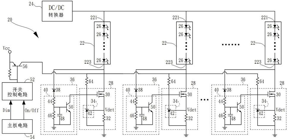
[0053] see figure 2 , figure 2 It is a circuit diagram of a preferred embodiment of the LED driving circuit 20 of the present invention. In general, the LED driving circuit 20 can be applied to liquid crystal display products using a light source composed of LEDs as a backlight source. The LED driving circuit 20 is used to drive a light source composed of a plurality of LED strings 22 , wherein each LED string 22 includes a plurality of LEDs 26 coupled in series. Each LED light string 22 has an input end 221 and an output end 223 respectively. The input ends 221 of all LED light strings 22 are coupled to a DC voltage output by a DC / DC converter 24 .

[0054] The LED driving circuit 20 includes a plurality of constant current circuits 28 , wherein each constant current circuit 28 includes a transistor 30 , a detection resistor 32 and a feedback circuit 34 . The transistor 30 and the detection resistor 32 are coupled in series between the output terminal 223 of a correspond...


PUM


Abstract

The invention relates to a light emitting diode driving circuit for driving a plurality of light emitting diode chains. The light emitting diode driving circuit comprises a plurality of constant current circuits and a plurality of short-circuit protection circuits; a transistor and a detection resistor in each constant current circuit are coupled in series between the output end and the ground end of a corresponding light emitting diode chain; and when the constant current circuits work normally, by comparing a reference voltage with a detection voltage generated by the detection resistor, a feedback circuit in each constant current circuit outputs a signal to control the size of current passing through the transistor to achieve constant current control; in addition, each short-circuit protection circuit is coupled with the output end of the corresponding light emitting diode chain and the corresponding constant current circuit and is used for outputting a short circuit signal to cut off the transistor of the corresponding constant current circuit to turn off the corresponding light emitting diode chain when the voltage of the output end of the corresponding light emitting diode chain reaches a preset voltage and the voltage of the input end of a short circuit signal generation circuit in the short-circuit protection circuit reaches a preset voltage.

Description

technical field [0001] The invention relates to a light-emitting diode drive circuit, in particular to a light-emitting diode drive circuit with a short-circuit protection function. Background technique [0002] Today's liquid crystal display products have gradually begun to use a light source composed of light-emitting diodes as a backlight source. see figure 1 , figure 1 It is a circuit diagram of an existing LED driving circuit 10 . The LED driving circuit 10 is used to drive a plurality of LED light strings 22 , wherein each LED light string 22 includes a plurality of LED light strings 26 coupled in series. A light source composed of a plurality of LED light strings 22 can be applied as a backlight light source for liquid crystal display products. Each LED light string 22 has an input end 221 and an output end 223 respectively, and the input ends 221 of all LED light strings 22 are coupled to a DC voltage output by a DC / DC converter 24 . The LED drive circuit 10 can...

Claims


Application Information

Patent Timeline
IPC IPC(8): G09G3/34G09G3/36
Inventor 余祚尚李宗晏
Owner TPV ELECTRONICS (FUJIAN) CO LTD
Why Eureka
Try Eureka