Mechanical loading flow chamber device for co-culturing in-vitro cells

A cell culture, flow chamber technology, applied in the field of biomechanical engineering research, can solve problems such as inappropriate multi-view cell biomechanics

Inactive Publication Date: 2011-01-12
BEIHANG UNIV
View PDF7 Cites 15 Cited by
  • Summary
  • Abstract
  • Description
  • Claims
  • Application Information

AI Technical Summary

Problems solved by technology

[0005] The above-mentioned flow chambers can only realize the co-culture of cells without applying shear stress, or only apply shear stress to one type of cell in the co-culture, and cannot independently apply mechanical stimulation to the two cells during cell co-culture. It is suitable for the current study of multi-view cell biomechanics, with scientific research limitations

Method used


Image

  • Mechanical loading flow chamber device for co-culturing in-vitro cells
  • Mechanical loading flow chamber device for co-culturing in-vitro cells
  • Mechanical loading flow chamber device for co-culturing in-vitro cells

Examples


Embodiment Construction

[0026] The present invention will be described below in conjunction with the accompanying drawings and embodiments.

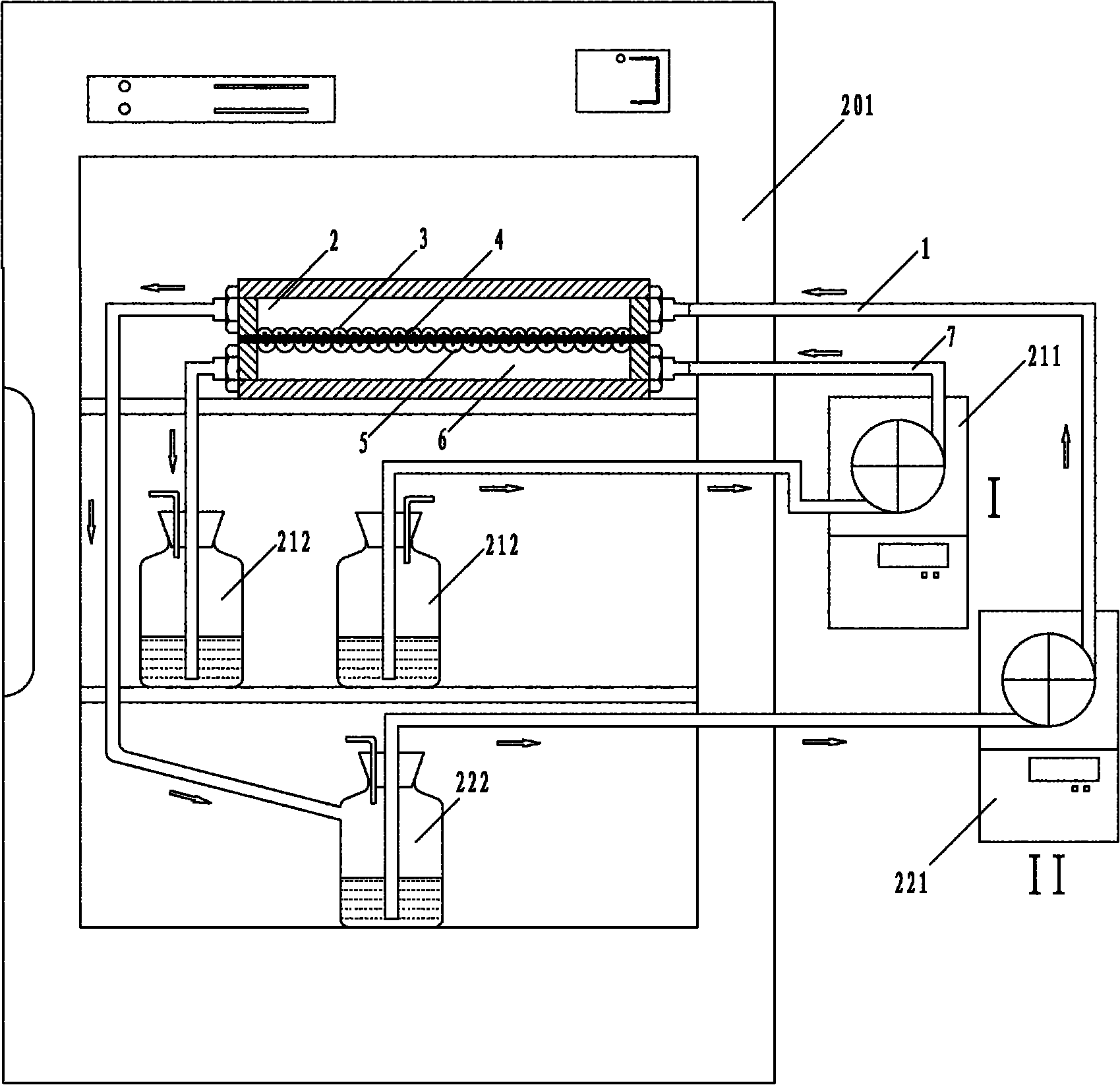
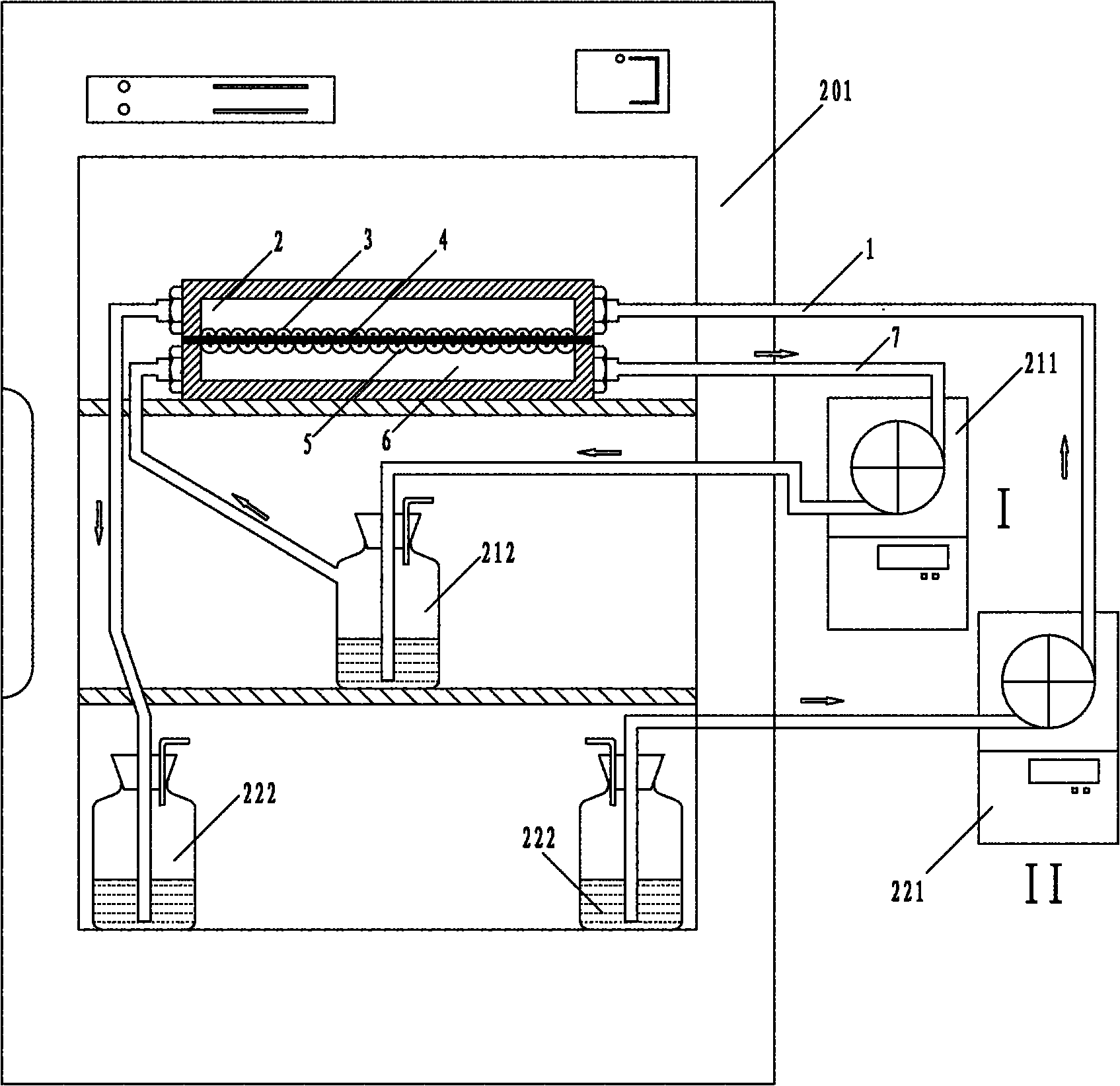
[0027] In the parallel plate flow chamber, the relationship between shear force, circulating fluid flow rate, circulating fluid viscosity and flow chamber size is: τ=6μQF / WH 2 .

[0028] F depends on the aspect ratio (W / H) of the flow chamber, and when W / H>>1, F≈1. Where τ is the shear stress at the bottom of the flow chamber (dyn / cm 2 ); μ is the perfusate viscosity (dyn s / cm 2 ); Q is the flow rate (cm 3 / s); W is the width of the flow chamber (cm); H is the height of the flow chamber (cm). In the system according to one embodiment of the present invention, the culture medium contains 10% FBS, and the perfusate viscosity μ is the dynamic viscosity, with a value of 0.013 dyn s / cm 2 . In the experiment, the dimensions of the two flow chambers are both W=3cm and H=0.05cm. When shear stress τ=15dyn / cm 2 , Q=τWH 2 / 6μF≈1.4423cm 3 / s.

[0029] The Reynol...


PUM


Abstract

The invention provides a mechanical loading flow chamber device for co-culturing in-vitro cells. The device comprises an upper flow chamber, a lower flow chamber, a permeable film, a first perfusion system and a second perfusion system, wherein the permeable film is arranged between the upper flow chamber and the lower flow chamber and used for separating the upper and lower flow chambers and two kinds of different cells can be inoculated onto the upper surface and the lower surface of the permeable film; the first perfusion system is communicated with the upper flow chamber through a first passage way; and the second perfusion system is communicated with the lower flow chamber through a second passage way. In the invention, micropores of the permeable film allow the two kinds of co-cultured cells to be connected through synapses and keep mutually permeated perfusates in the upper and lower chambers in seepage balance so that cytokines are vertically diffused. The upper and lower chambers can apply flow shear stresses onto the cells on the two sides of the film respectively, so that the two kinds of cells can bear the shear stress while being co-cultured on line respectively. The device can culture two kinds of different cells in vitro in the same environment and can apply double shear stresses in different modes onto the two kinds of cells at the same time.

Description

technical field [0001] The invention relates to the field of biomechanical engineering research, in particular to a flow chamber device capable of co-cultivating two kinds of cells and loading two kinds of independent shear stresses on the two kinds of cells. Background technique [0002] As an emerging interdisciplinary subject, biomechanics has attracted more and more attention from the academic community, and flow chambers have also been widely used as a mechanical loading device in the study of cell mechanics in in vitro flow environments. The initial steady flow flow chamber was designed by Frangos, Eskin et al. (Eskin SG, Ives CL, Mcintire LV, et al. Response of cultured endothelial cells to steady flow[J]. Microvasc Res, 1984, 28: 87-94; Frangos JA, Eskin SG, Mcintire LV, et al.Flow effect on prostacyclin production by cultured human endothelial cues[J].Science, 1985, 227:1477-1479.), in the early studies, the flow chambers used by scientists were This single channel...

Claims


Application Information

Patent Timeline
Patent Type & Authority Applications(China)
IPC IPC(8): C12M3/00C12M1/36
Inventor 樊瑜波孙联文杨肖蒲放贡向辉
Owner BEIHANG UNIV
Why Eureka
Try Eureka