Unlock instant, AI-driven research and patent intelligence for your innovation.

Display device

A display device and display surface technology, which is applied to identification devices, optics, instruments, etc., can solve problems such as inability to use POS terminals, business inconvenience, and difficulty for users to handle by themselves.

Inactive Publication Date: 2011-01-12
TOSHIBA TEC KK
View PDF5 Cites 4 Cited by
  • Summary
  • Abstract
  • Description
  • Claims
  • Application Information

AI Technical Summary

Problems solved by technology

However, since the display device needs to be disassembled to remove the dust, it is difficult for the user to handle it by himself, and the maintenance personnel dispatched by the maintenance service company need to disassemble the display device to remove the dust.
In such a processing method, since the POS terminal cannot be used temporarily, it may cause inconvenience to the business
In addition, since this problem is related to a single surface of the touch panel on the display panel side, it is difficult to apply the technique of the aforementioned Japanese Patent Application Laid-Open No. 8-185560 that properly maintains the hygienic state of the touch panel side.

Method used


Image

  • Display device
  • Display device
  • Display device

Examples


no. 1 example

[0022] Hereinafter, a first embodiment will be described with reference to the drawings.

[0023] In addition, in this embodiment, the display device provided in the POS terminal 1 used for settlement processing in various goods sales stores is demonstrated as an example.

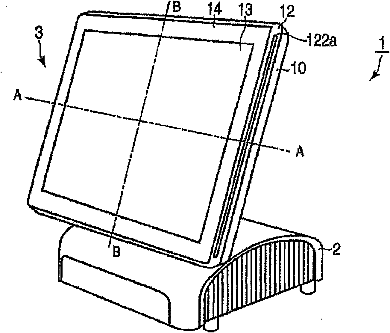
[0024] use Figure 1 ~ Figure 4 The configuration of the POS terminal 1 will be described.

[0025] figure 1 It is an external perspective view of the POS terminal 1 . The POS terminal 1 is composed of a base unit 2 and a display device 3 . The base part 2 is equipped with a CPU (Central Processing Unit: central processing unit) that functions as a control center, a ROM (Read Only Memory: Read Only Memory) that stores fixed data, and a RAM (Random Access Memory: Random Access Memory) that forms storage areas for various operations. access memory), and a control circuit composed of controllers of various devices included in the POS terminal 1 .

[0026] figure 2 is an exploded perspective view showing...

no. 2 example

[0045] Next, refer to Figure 7 A second embodiment will be described.

[0046] This embodiment differs from the first embodiment in that the peep prevention film is attached to the display device 3 . In addition, the same parts as those in the first embodiment are assigned the same symbols and their descriptions are omitted.

[0047] Figure 7 It is an exploded perspective view of the display device 3 . The display device 3 of the present embodiment has a substantially rectangular flat-shaped peep prevention film 15 formed between the LCD panel 11 and the touch panel 13 to cover the entire size of the display unit 111 .

[0048] The peep prevention film 15 is formed of a substantially transparent member such as a louver film, for example, by sandwiching a louver between substantially transparent front and rear substrates. The louver has a plurality of tiny louvers, and the advancing direction of the transmitted light is restricted within a predetermined emission angle ran...


PUM


Abstract

On a circumferential edge part of a display panel having a display surface, a front bezel having an aperture through which a cleaning member for removing dust adhering to the display surface can be freely inserted and removed is provided. Moreover, a touch panel is provided on the front bezel in such a manner that the touch panel is arranged to face the display surface of the display panel with a gap formed between the display surface and the touch panel.

Description

[0001] This application claims the priority right of application number JP2009-157042 and the filing date is July 1, 2009, and all the contents of the above documents are cited in this application. technical field [0002] The present invention relates to a display device in which a touch panel is provided on a display surface such as an LCD (Liquid Crystal Display). Background technique [0003] In recent years, electronic equipment including a display device in which a touch panel is provided on a display surface such as an LCD panel has been widely used. [0004] However, there is a problem of unsanitary conditions in the display devices of devices used by unspecified many people, such as automatic teller machines installed in banks and public facilities, as the touch surfaces gradually become dirty due to use. [0005] As a prior art for dealing with such a problem, an input device described in Japanese Patent Application Laid-Open No. 8-185560 is known. In this input d...

Claims


Application Information

Patent Timeline
Patent Type & Authority Applications(China)
IPC IPC(8): G09F9/00G09F9/35G07G1/12G06F3/041
CPCG06F3/041G06F1/1601G07G1/01G02F2001/133311G02F1/13338G02F1/133311
Inventor 齐藤义弘
Owner TOSHIBA TEC KK