Cabinet door locking device with emergency opening function

A locking device, emergency opening technology, applied in building locks, door/window accessories, handle connections, etc., can solve the problem of not having the function of opening the safe, and achieve the effect of ensuring safety

Active Publication Date: 2011-01-26
TRI STAR
View PDF4 Cites 5 Cited by
  • Summary
  • Abstract
  • Description
  • Claims
  • Application Information

AI Technical Summary

Problems solved by technology

However, commonly used safes can only be opened/closed from the outside, and generally do not have the function of opening from the inside of the safe
Therefore, when the user is alone in the

Method used


Image

  • Cabinet door locking device with emergency opening function
  • Cabinet door locking device with emergency opening function
  • Cabinet door locking device with emergency opening function

Examples


Embodiment 1

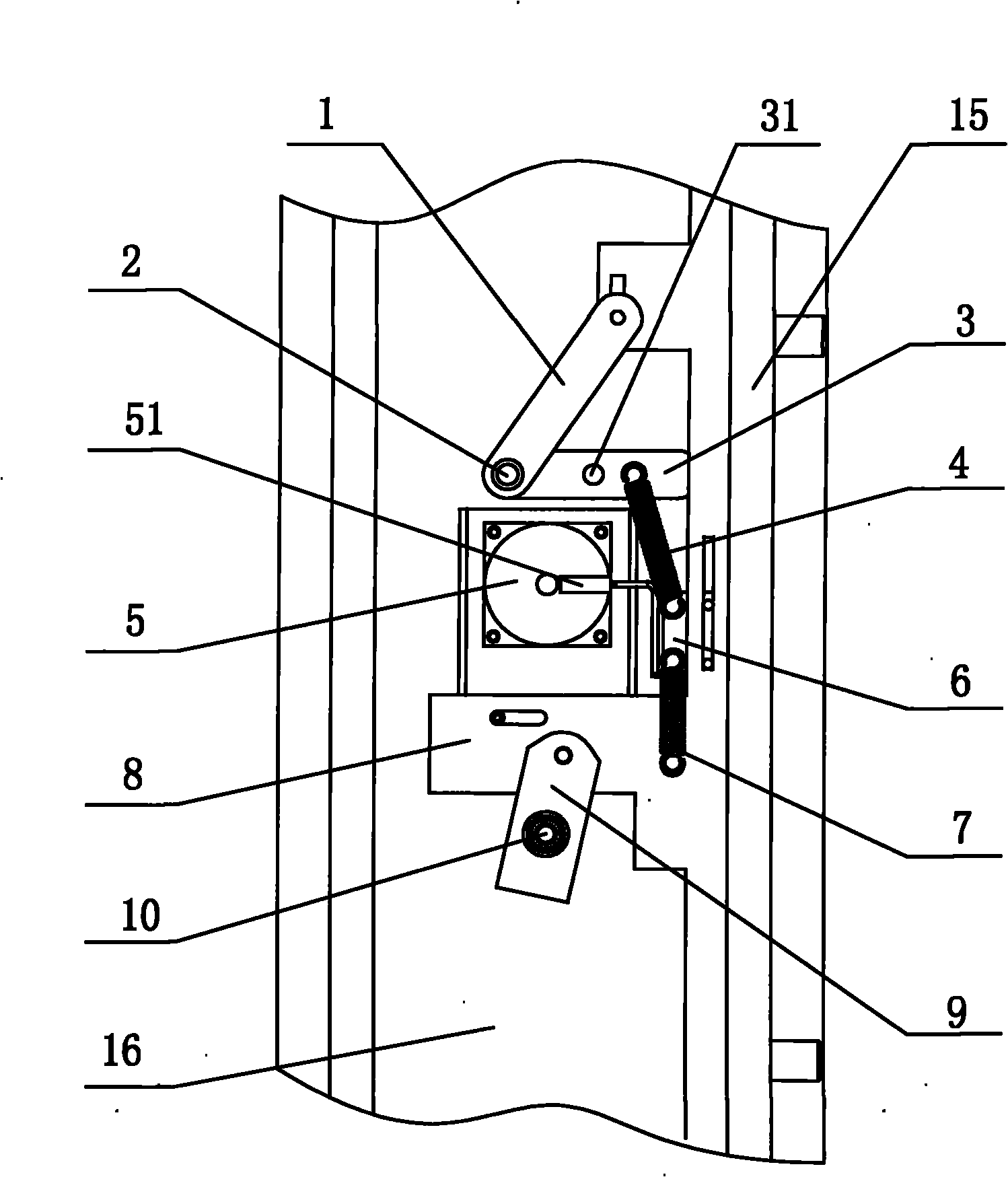
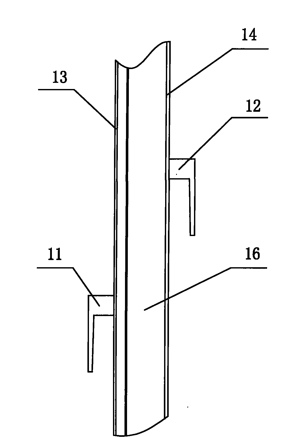
[0027] like figure 1 and image 3 As shown, when the lock 5 of the present invention is a mechanical lock, the structural schematic diagram of the cabinet door locking device with emergency opening is disclosed. It can be seen from the figure that the elastic pre-locking device of the lock 5 is a bolt return spring 7. The two ends of deadbolt return spring 7 are respectively connected with linkage plate 8 and deadbolt 6, and described linkage plate 8 is provided with horizontal guide groove, first vertical guide groove and second vertical guide groove, and described linkage plate 8 is installed The horizontal guide nails in the horizontal guide groove are positioned and installed on the cabinet door, the dead bolt 6 is positioned and installed by the first vertical guide nails installed in the first vertical guide groove and the linkage plate 8, and the circular linkage plate 1 One end of the circular linkage plate 1 is positioned and installed on the cabinet door, and the ot...

Embodiment 2

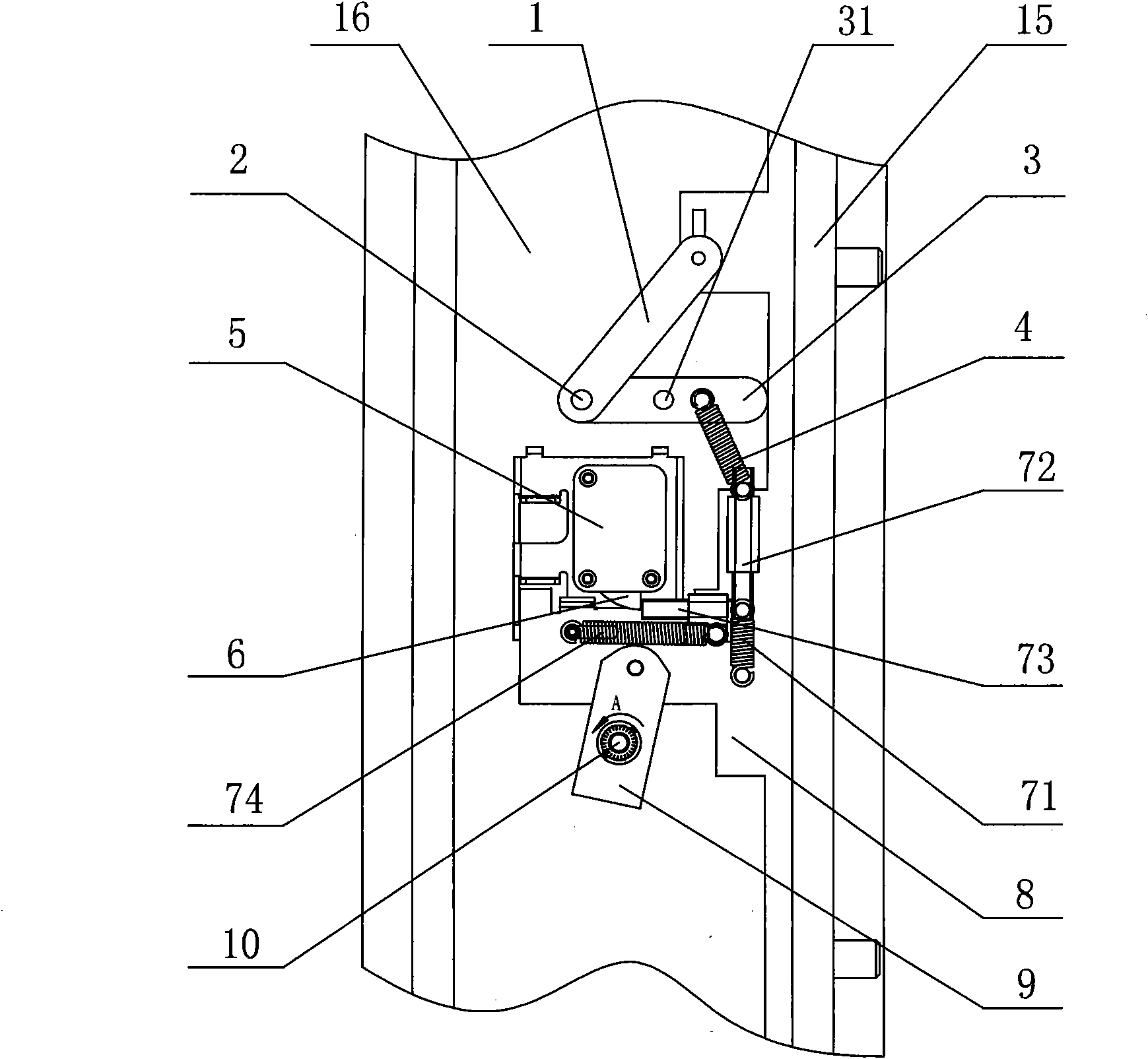
[0032] like figure 2 and image 3 It can be known that it discloses the lock 5 of the present invention is an electronic lock, and the structural schematic diagram of the cabinet door locking device with emergency opening is locked. It can be seen from the figure that the lock 5 is an electronic lock, and the lock 5 is elastically The locking device includes a first moving plate 72, a second moving plate 73, a pull spring 71 and a left pull spring 74, and the linkage plate 8 is also provided with a horizontal guide mount, a second vertical guide groove and a vertical guide mount, so The first moving plate 72 and the second moving plate 73 are respectively placed in the vertical guiding mounting seat and the horizontal guiding mounting seat, the vertical guiding mounting seat is a guide tube fixed longitudinally on the linkage plate 8, and the horizontal guiding mounting Seat then is the guide tube that is horizontally fixedly installed on the linkage plate 8, then when movin...


PUM


Abstract

The invention discloses a cabinet door locking device with an emergency opening function, comprising a lockset and a cabinet door locking/unlocking device, wherein the lockset comprises a lock body and a locking dog locked/unlocked with the lock body; the cabinet door locking/unlocking device comprises an external locking/unlocking device and an emergency unlocking device; the external locking/unlocking device comprises an external handle, a linking arm, a linking plate, a latch fixed plate and a lockset elastic pre-locking device; a rotating shaft of the external handle, the linking arm, the linking plate, the latch fixed plate and the lockset elastic pre-locking device are connected in a linking manner; the emergency unlocking device comprises a circular lining plate, a square linking plate, an emergency rotating shaft, a rotating shaft driving device and a connecting tension spring in a linking manner; and the rotating shaft driving device, the emergency rotating shaft, the square linking plate, the circular linking plate, the connecting tension spring and the lockset elastic pre-closing device are connected in a linking manner. Therefore, with the scheme, the emergency opening of the cabinet door can be realized by using the emergency unlocking device and the phenomenon that the cabinet door cannot be opened due to the self-locking of the lockset can be avoided.

Description

technical field [0001] The invention relates to a lock, in particular to a cabinet door locking device with emergency opening. Background technique [0002] At present, most safe doors only have a single lock, which is opened or locked on the outside of the cabinet door. Therefore, when the lock is self-locking and cannot be opened, it will cause inconvenience to the user. Therefore, a lock that is currently commonly used is required. (such as mechanical locks or electronic locks, etc.) are used in conjunction with emergency opening devices equipped with common locks for emergency opening, so as to avoid the phenomenon that the cabinet door cannot be opened when it is locked. [0003] In addition, the application of safes is more and more extensive, and its anti-theft effect is more and more remarkable. However, commonly used safes can only be opened / closed from the outside, and generally do not have the function of opening from the inside of the safe. Therefore, when the ...

Claims


Application Information

Patent Timeline
IPC IPC(8): E05B17/22E05B65/52E05B3/00
Inventor 刘佳炎雍丛霞王晓阳顾春浩褚国荣赵建房海东杜浩然
Owner TRI STAR
Why Eureka
Try Eureka