Complex machining center

A composite machining center and machining unit technology, applied in the direction of metal processing equipment, manufacturing tools, and other manufacturing equipment/tools, can solve the problems of reduced productivity, a large amount of labor time, and the inability to operate auxiliary shaft equipment 20, etc., to improve work efficiency , The effect of improving processing efficiency

Inactive Publication Date: 2011-01-26
金福仁
View PDF0 Cites 44 Cited by
  • Summary
  • Abstract
  • Description
  • Claims
  • Application Information

AI Technical Summary

Problems solved by technology

Thus, while the main shaft device 10 is being operated, the sub shaft device 20 cannot be operated, so several operations cannot be performed simultaneously; the sub shaft device 20 can only be operated after the main shaft device 10 is completed
Thus, processing work is complicated, requiring a lot of manpower and a lot of time
As a result, the productivity of the machine is significantly reduced
[0009] Also, although different tools are attached to the main shaft device 10 and the sub shaft device 20 respectively, only operations allowed by the fixable tool can be performed

Method used


Image

  • Complex machining center
  • Complex machining center
  • Complex machining center

Examples


Embodiment Construction

[0039] Embodiments of the present invention will be described in detail below with reference to the accompanying drawings.

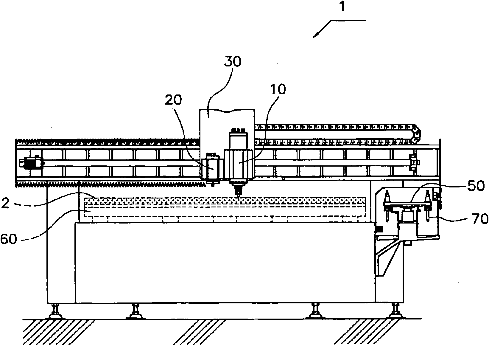
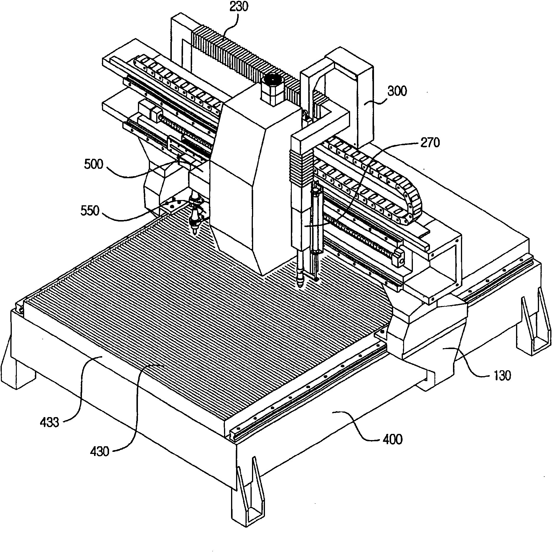
[0040] The compound machining center according to the present invention comprises a base frame 400, an X-direction positioning block 130 installed on the base frame 400, at least one Y-direction positioning block 150 arranged on at least one side of the X-direction positioning block 130, and a Y-direction positioning block 150 located on the Y-direction positioning block 130. At least one Z direction positioning block 610 , 650 in front of the direction positioning block 150 .

[0041] The workbench 433 is arranged on the base frame 400 .

[0042] The table 433 disposed on the base frame 400 can be reciprocated by the transfer unit 700 in the longitudinal direction of the base frame.

[0043] In an exemplary embodiment, the rotation table 450 connected to the second rotation unit 470 may be disposed on the work table 433 .

[0044] The second rotating ...


PUM


Abstract

The present invention relates to a complex machining center in which at least one machining unit is mounted on one or more X-direction positioning blocks which are fixed or movable about a base frame, one or more Y-direction positioning blocks arranged on at least one side of the X-direction positioning block, and a Z-direction positioning block connected to the Y-direction positioning block in such a manner that the Z-direction positioning block is movable in the upward and downward directions. The complex machining center is capable of performing carving, precision cutting, V-shape cutting and groove forming work.

Description

technical field [0001] The present invention relates to a compound machining center constructed so that engraving, precision cutting, V-cutting and grooving work can be performed by a single machining center. Background technique [0002] Typically, CNC milling machines include a Z-axis slide with a single spindle. When processing the target, various tools with different functions must be fixed to the tool holder in sequence according to the sequence of the processing technology. [0003] At the completion of each process, the tool must be replaced by another tool required for the subsequent process by rotating the tool holder. After that, the Z-axis slider and the spindle operate according to the preset program and implement a series of CNC operations. [0004] Also, the manipulation of the machining object typically requires repeated cutting operations rather than the machining operation being performed by a single cutting operation. As each cutting operation is perform...

Claims


Application Information

Patent Timeline
Patent Type & Authority Applications(China)
IPC IPC(8): B23P23/04B23C1/08B23P23/02B23P23/00B23C3/00
Inventor 金福仁
Owner 金福仁
Why Eureka
Try Eureka