Check patentability & draft patents in minutes with Patsnap Eureka AI!

Imaging apparatus

A camera device and lens frame technology, which can be used in installation, image communication, television, etc., can solve problems such as inaccurate focus positions, and achieve the effect of improving photography accuracy and convenience

Inactive Publication Date: 2011-01-26
SANYO ELECTRIC CO LTD
View PDF1 Cites 5 Cited by
  • Summary
  • Abstract
  • Description
  • Claims
  • Application Information

AI Technical Summary

Problems solved by technology

Therefore, if the lens cannot be properly positioned in the original position, there may be inaccuracies in the focus position.

Method used


Image

  • Imaging apparatus
  • Imaging apparatus
  • Imaging apparatus

Examples


Embodiment Construction

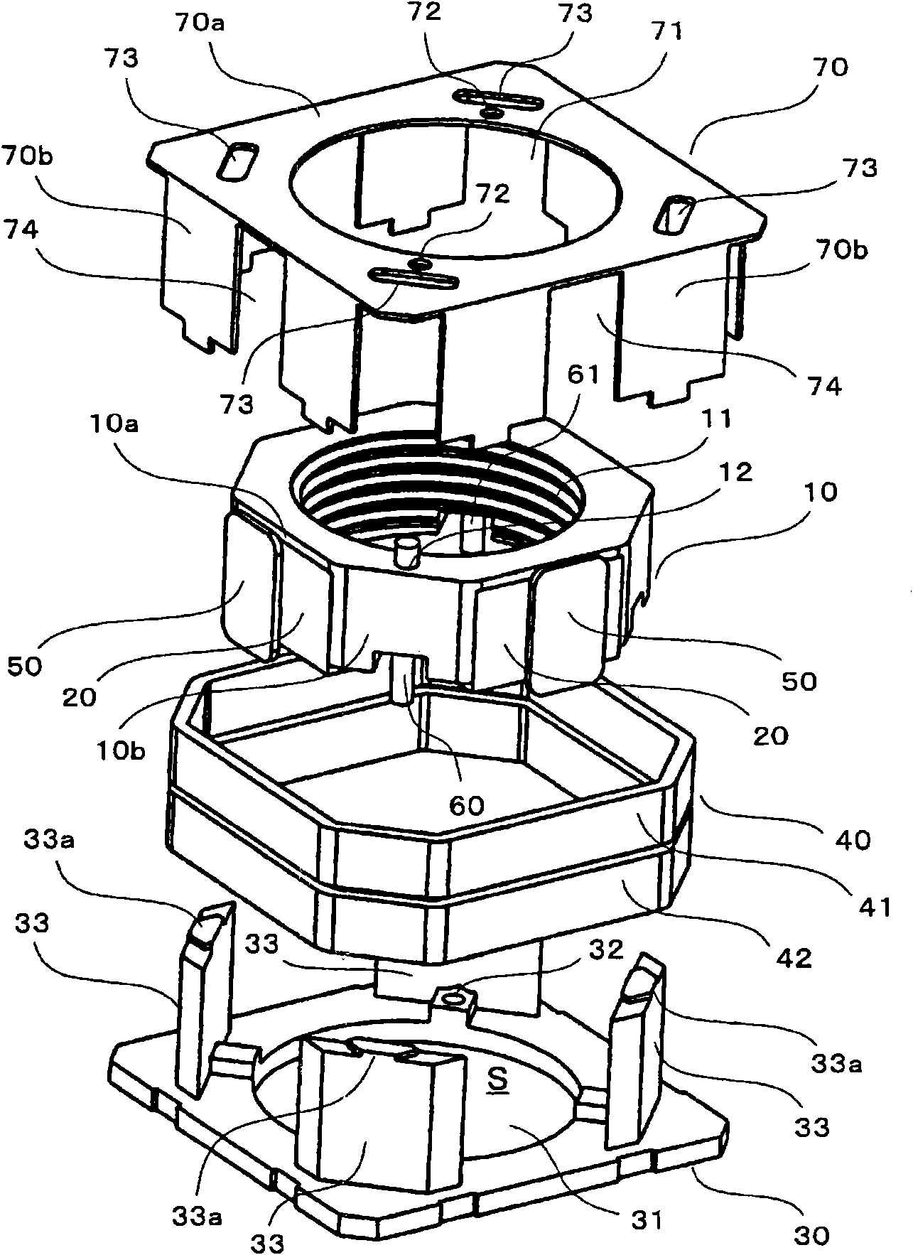
[0039] Hereinafter, embodiments according to the present invention will be described with reference to the accompanying drawings. The imaging apparatus of the present embodiment is an imaging apparatus to which the present invention is applied to an imaging apparatus that does not have an autofocus function. That is, in the present embodiment, the position of the lens is switched and fixed to two positions, such as the position for normal shooting (standard position) and the position for macro shooting (macro position). Here, the imaging device includes a so-called macro switching lens driving device capable of switching the lens position between the standard position and the macro position.

[0040] figure 1 It is an exploded perspective view of the lens drive device which concerns on embodiment. figure 2 It is a figure which shows the structure of the lens drive device after assembly. The figure (a) is a figure of the completed assembly, and the figure (b) is a figure of...


PUM


Abstract

Provided is an imaging apparatus wherein a lens can be located at a desired position properly at the time of focus adjustment, and accuracy of focus adjustment can be enhanced. At the time of normal photography, a lens holder (10) is located at a normal position and abutting against a base (30). When the lens holder (10) is displaced to a macro position, a long pulse signal is applied to a coil (40), at first. Consequently, the lens holder (10) is displaced to a position near the macro position. Subsequently, a short pulse signal is applied a plurality of times to the coil (40). Consequently, the lens holder (10) approaches the macro position gradually and is located eventually at the macro position by abutting against a cover (70). The lens holder (10) located at the normal position or the macro position is held in place by attraction of a magnet (20) and a magnetic plate (50) and frictional force of a shaft (60) and a round hole (12).

Description

technical field [0001] The present invention relates to an imaging device, and more particularly, to an imaging device suitable for a camera, a mobile phone with a camera function, or the like. Background technique [0002] Some mobile phones with camera functions have a so-called "macro photography function" for photographing objects from adjacent positions, in addition to the photographing function for photographing the subject from a certain distance away. In this case, the imaging device mounted in the mobile phone has a structure for switching the lens position during normal photography and during macro photography. That is, in this configuration, the lens is fixed to the first position during normal shooting, and is fixed to the second position closer to the object to be photographed than the first position during macro shooting. For example, Patent Document 1 discloses an example of an imaging device having such a structure. [0003] In the outer frame member of the...

Claims


Application Information

Patent Timeline
IPC IPC(8): G02B7/08G02B7/105H04N5/225
CPCG02B7/102G02B13/001H04N5/23212H04N5/2254H04N23/55H04N23/673
Inventor 山下博司
Owner SANYO ELECTRIC CO LTD
Features
  • R&D
  • Intellectual Property
  • Life Sciences
  • Materials
  • Tech Scout
  • Unparalleled Data Quality
  • Higher Quality Content
  • 60% Fewer Hallucinations
Learn More