Brightness sensing system and illumination system using same

A technology of brightness sensing and brightness, which is applied to the components of TV systems, lighting devices, and the method of comparing with reference electrical parameters, etc., which can solve problems such as the difficulty of accurately detecting the brightness of the target space

Inactive Publication Date: 2011-02-02
PANASONIC CORP
View PDF6 Cites 1 Cited by
  • Summary
  • Abstract
  • Description
  • Claims
  • Application Information

AI Technical Summary

Problems solved by technology

As a result, it is sometimes difficult to accurately detect the brightness of the target space

Method used


Image

  • Brightness sensing system and illumination system using same
  • Brightness sensing system and illumination system using same
  • Brightness sensing system and illumination system using same

Examples


Embodiment Construction

[0019] Below, will refer to Figure 1 to Figure 3C A brightness sensing system according to an embodiment of the present invention and a lighting system using the same are described, Figure 1 to Figure 3C form a part of these examples.

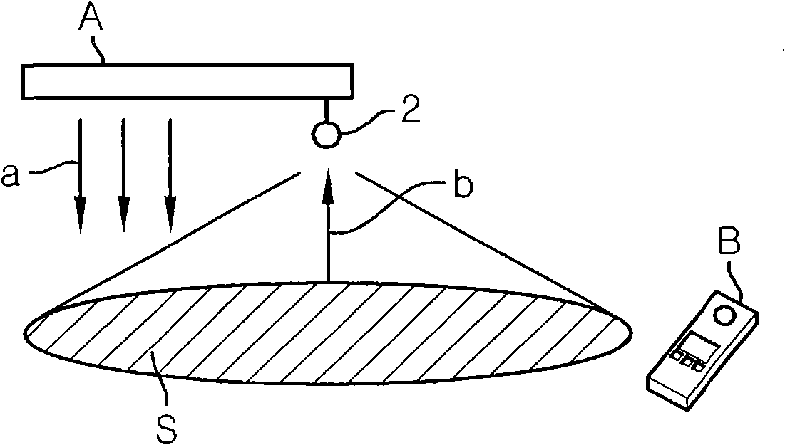
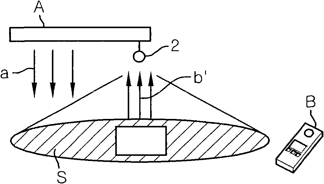
[0020] The luminance sensing system in this embodiment is used to detect the luminance (illuminance) of a specific irradiated surface S, from such as Figures 2A to 2C Light from lighting device A shown in irradiates the surface. The lighting system in this embodiment is designed to maintain the illuminance on the irradiated surface S at a substantially constant level by using a brightness sensing system.

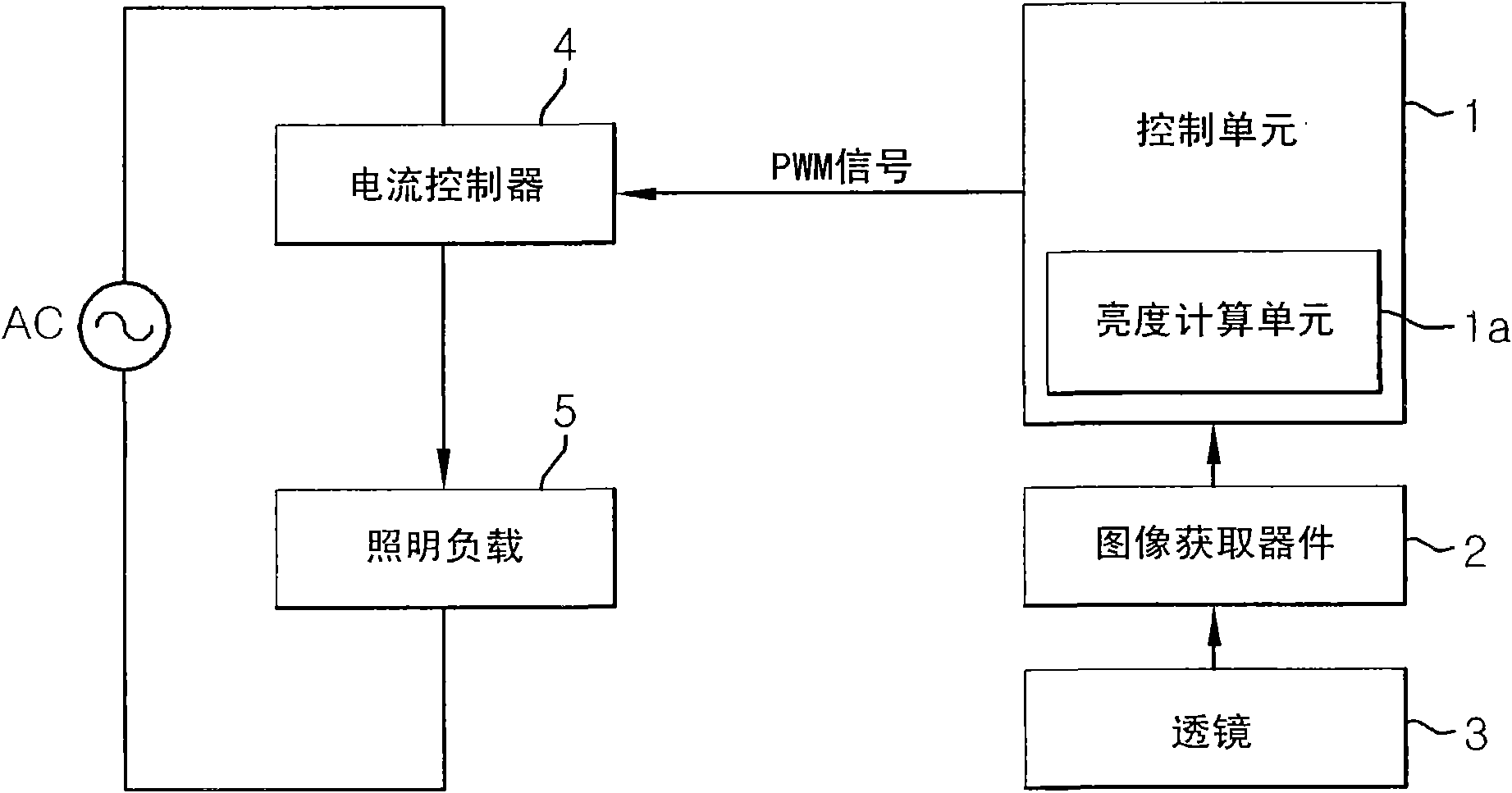
[0021] refer to figure 1 , the brightness sensing system of the present embodiment includes: an image acquisition device (or image acquisition unit) 2 formed by, for example, a CCD sensor or a CMOS sensor; a lens 3 for determining the field of view of the image acquisition device 2; and a control unit 1, A luminance calculation unit 1a...


PUM


Abstract

A brightness sensing system includes an image pickup unit for taking an image of a target space and a calculation unit for calculating the brightness of an image pickup area based on the image taken by the image pickup unit. In the brightness sensing system, if the difference or the ratio between an image as a whole and a pixel block formed of one or more pixels is equal to or greater than a threshold in terms of brightness change between a previously-taken reference image and a currently-taken target image, the calculation unit excludes the pixel block from comparison candidates and compares the brightness of the target image with the brightness of the reference image based on the remaining pixels other than the pixel block.

Description

technical field [0001] The present invention relates to a brightness sensing system and a lighting system using the same. Background technique [0002] Conventionally, a CCD (Charge Coupled Device) is used as a sensor for sensing brightness in known lighting systems (for example, see Japanese Patent Application Laid-Open No. 2004-501496, paragraph [0016] and FIG. 3 ). In this lighting system, the brightness of an image acquisition area is calculated by averaging the brightness of light detected by pixels in image data captured by a CCD camera. Based on the results of this calculation, the dimming level of the lighting device is increased or decreased to thereby maintain the illuminance of the target space at a substantially constant level. [0003] In the above lighting system, if the reflectivity of the target space is changed, for example by a piece of white paper placed on the table, the brightness of the detection is increased. Thus, it may be difficult to maintain the...

Claims


Application Information

Patent Timeline
Patent Type & Authority Applications(China)
IPC IPC(8): H05B37/02G01J1/18G03B7/00G03B15/03G03B15/035
CPCH04N5/2351H04N5/2354H04N23/71H04N23/74
Inventor 谷川哲也松田真二川岛寿一
Owner PANASONIC CORP
Why Eureka
Try Eureka