Rotary mobile phone
A rotary, mobile phone technology, applied in the direction of telephone structure, wireless communication, electrical components, etc., can solve the problems of complex structure, affecting the service life of mobile phone products, and easy damage to the flexible circuit board of the electrical connection line, and achieves a simple structure. Effect
- Summary
- Abstract
- Description
- Claims
- Application Information
AI Technical Summary
Benefits of technology
Problems solved by technology
Method used
Image

Examples
Embodiment approach 1
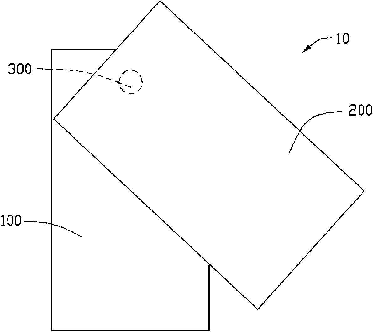
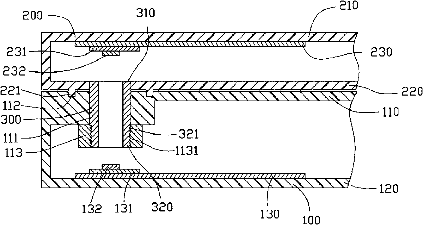
[0012] see figure 1 and figure 2 , the present invention provides a rotary mobile phone 10 , which includes a host 100 , a cover 200 and a rotating shaft 300 . The host 100 is connected to the cover 200 through the rotating shaft 300 .
[0013] The host 100 is provided with a keyboard, a microphone, etc., and includes a first upper wall 110 , a first lower wall 120 and a host circuit board 130 . A shaft hole 111 is formed on the first upper wall 110 , and an annular slide groove 112 is formed around the shaft hole 111 on the outer surface of the first upper wall 110 . One end of the shaft hole 111 close to the first lower wall 120 is provided with a screw sleeve 113, the screw sleeve 113 is a hollow ring-shaped structure, and an internal screw 1131 is formed inside it for fixing the Rotating shaft 300. The host circuit board 130 is electrically connected to the keyboard on the host 100 , and the host circuit board 130 is arranged in the host 100 and on the first lower wal...
Embodiment approach 2
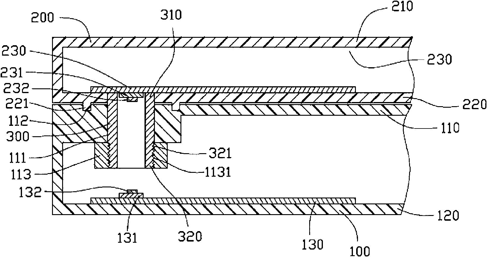
[0017] see image 3 , which is a schematic structural diagram of the rotary mobile phone 10 according to the second embodiment of the present invention. The difference between the second embodiment and the first embodiment is that the cover circuit board 230 is arranged on the second lower wall 220 of the cover 200 , while the second photoelectric converter 231 and the photoreceptor 232 It is accommodated in the first end 310 of the rotating shaft 300 , and the light receiver 232 is disposed facing the cavity of the rotating shaft 300 . The light transmitter 132 and the light receiver 232 perform signal transmission through the cavity of the rotating shaft 300 to realize the signal transmission between the host 100 and the cover 200 . In this embodiment, by disposing the cover circuit board 230 on the second lower wall 220 of the cover 200 , the second upper wall 210 and the second lower wall 220 of the cover 200 can be The distance between them is reduced, thereby reducing ...
Embodiment approach 3
[0019] see Figure 4 , which is a schematic structural diagram of the rotary mobile phone 10 according to the third embodiment of the present invention. The difference between the third embodiment and the first embodiment is that a plurality of optical collimator lenses 330 are arranged inside the rotating shaft 300 , and the optical collimator lenses 330 are connected with the light emitter 132 and the light receiver 232 Oppositely, it is used for converging the optical signal emitted by the optical transmitter 132 into parallel light, so as to transmit it to the optical receiver 232 . In this embodiment, two optical collimation lenses 330 are arranged inside the rotating shaft 300 . In this embodiment, by setting the optical collimator lens 330 in the cavity of the rotating shaft 300, the optical signal emitted by the optical transmitter 132 is converged into parallel light, so that the optical receiver 232 can The optical signal sent by the optical transmitter 132 is bett...
PUM
 Abstract
Description
Claims
Application Information
 - R&D Engineer
- R&D Manager
- IP Professional
- Industry Leading Data Capabilities
- Powerful AI technology
- Patent DNA Extraction
Browse by: Latest US Patents, China's latest patents, Technical Efficacy Thesaurus, Application Domain, Technology Topic.
© 2024 PatSnap. All rights reserved.Legal|Privacy policy|Modern Slavery Act Transparency Statement|Sitemap