

Board punching device
A punching device and plate technology, applied in the direction of grinding drive devices, grinding slides, wood processing equipment, etc., can solve the problems of heavy workload and low efficiency, achieve high positioning accuracy, reduce grinding processes, and reduce labor The effect of the process of clamping the workpiece
Pending Publication Date: 2018-10-12
重庆哲骁装饰工程有限公司
View PDF0 Cites 24 Cited by
- Summary
- Abstract
- Description
- Claims
- Application Information
AI Technical Summary
Problems solved by technology
[0003] The purpose of the present invention is to provide a board punching device to solve the problem of large workload and low efficiency caused by manual rotation and clamping of wooden boards
Method used
View moreImage
Smart ImageViewing Examples

Examples
Embodiment Construction
[0015] The present invention will be described in further detail below by means of specific embodiments:
Login to View More PUM
 Abstract
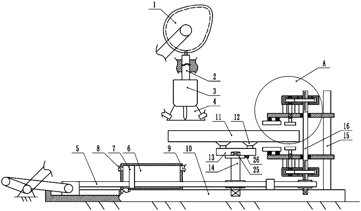
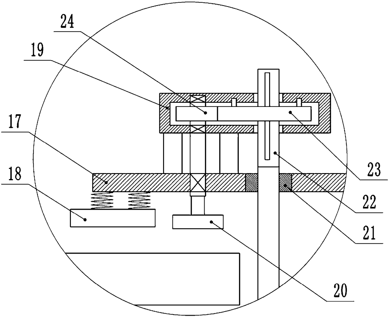
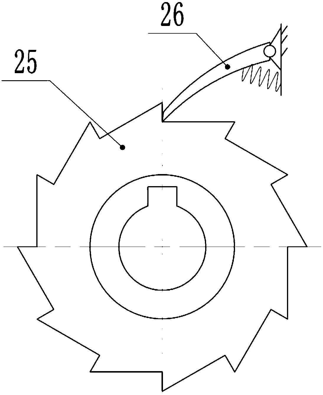
The invention belongs to the technical field of wood processing equipment, and particularly discloses a board punching device. The board punching device comprises a machine frame. A rotary table is arranged on the machine frame, a punching mechanism and a power mechanism are arranged on the upper portion of the machine frame, and the power mechanism drives the punching mechanism to ascend and descend. A crank and sliding block mechanism is arranged on the machine frame, a push rod which is fixedly connected with a sliding block is connected to the machine frame in a sliding mode, and an intermittent mechanism which drives the rotary table to conduct one-way intermittent rotation is connected between the push rod and the rotary table. A clamping mechanism is further arranged on the machineframe, and comprises a supporting rod. Two supporting plates are connected to the supporting rod in a sliding mode. A two-way lead screw is connected to the machine frame in a rotating mode, the two supporting plates are matched with the two-way lead screw through nuts, and the two-way lead screw and the push rod are connected through a gear and rack pair. Clamping plates and polishing discs are arranged on the inner sides of the two supporting plates, and transmission mechanisms which are used for driving the polishing discs to rotate are connected between the polishing discs and the two-waylead screw. By the adoption of the scheme, automatic rotation and clamping of a board are achieved in the drilling process, the working efficiency is high, and the labor intensity of workers is reduced.
Description
technical field [0001] The invention belongs to the technical field of wood processing equipment, in particular to a plate punching device. Background technique [0002] Today, jewelry is placed in jewelry display cabinets for consumers to watch or select. Existing jewelry display cabinets are generally made of conventional wood and metal mixed to meet the general environment for display and exhibition. When manufacturing display cabinets, it is usually necessary to punch holes in wood and metal to facilitate later assembly. The existing punching devices usually manually push the wooden boards to realize the punching of different positions of the wooden boards, but this method has certain safety hazards, high labor intensity, and low positioning accuracy, especially for round wooden boards. When drilling, it is necessary to ensure that the round wooden board rotates around the center of the circle, and the wooden board needs to be clamped before each drilling, resulting in ...
Claims
Login to View More Application Information
Patent Timeline
 IPC IPC(8): B27C9/04B27C3/02B27G3/00B24B9/18B24B47/12B24B41/06B24B41/02
CPCB27C9/04B24B9/18B24B41/02B24B41/06B24B47/12B27C3/02B27G3/00
Inventor邓月全
Owner重庆哲骁装饰工程有限公司