A stamping mechanism of a stamping machine

A technology of punching mechanism and punching machine, applied in the field of punching mechanism, can solve the problems of low punching quality, irregular shape of felt sheet, displacement, etc., and achieve the effect of smooth punching, high precision and avoiding displacement

Inactive Publication Date: 2018-09-04
海宁英和金属制品有限公司
View PDF6 Cites 2 Cited by
  • Summary
  • Abstract
  • Description
  • Claims
  • Application Information

AI Technical Summary

Problems solved by technology

In addition to being able to shape the workpiece, stamping also has the function of stamping and cutting, that is, it can punch the workpiece down according to the set stroke, such as stamping a circular felt sheet, and stamping through a cylindrical cutter head, but because the felt sheet is a flexible material , there will be displacement, deformation and other phenomena at the moment of stamping, resulting in irregular shape of the stamped felt sheet and low stamping quality

Method used


Image

  • A stamping mechanism of a stamping machine
  • A stamping mechanism of a stamping machine
  • A stamping mechanism of a stamping machine

Examples


Embodiment Construction

[0020] The following are specific embodiments of the present invention in conjunction with the accompanying drawings to further describe the technical solutions of the present invention, but the present invention is not limited to these embodiments.

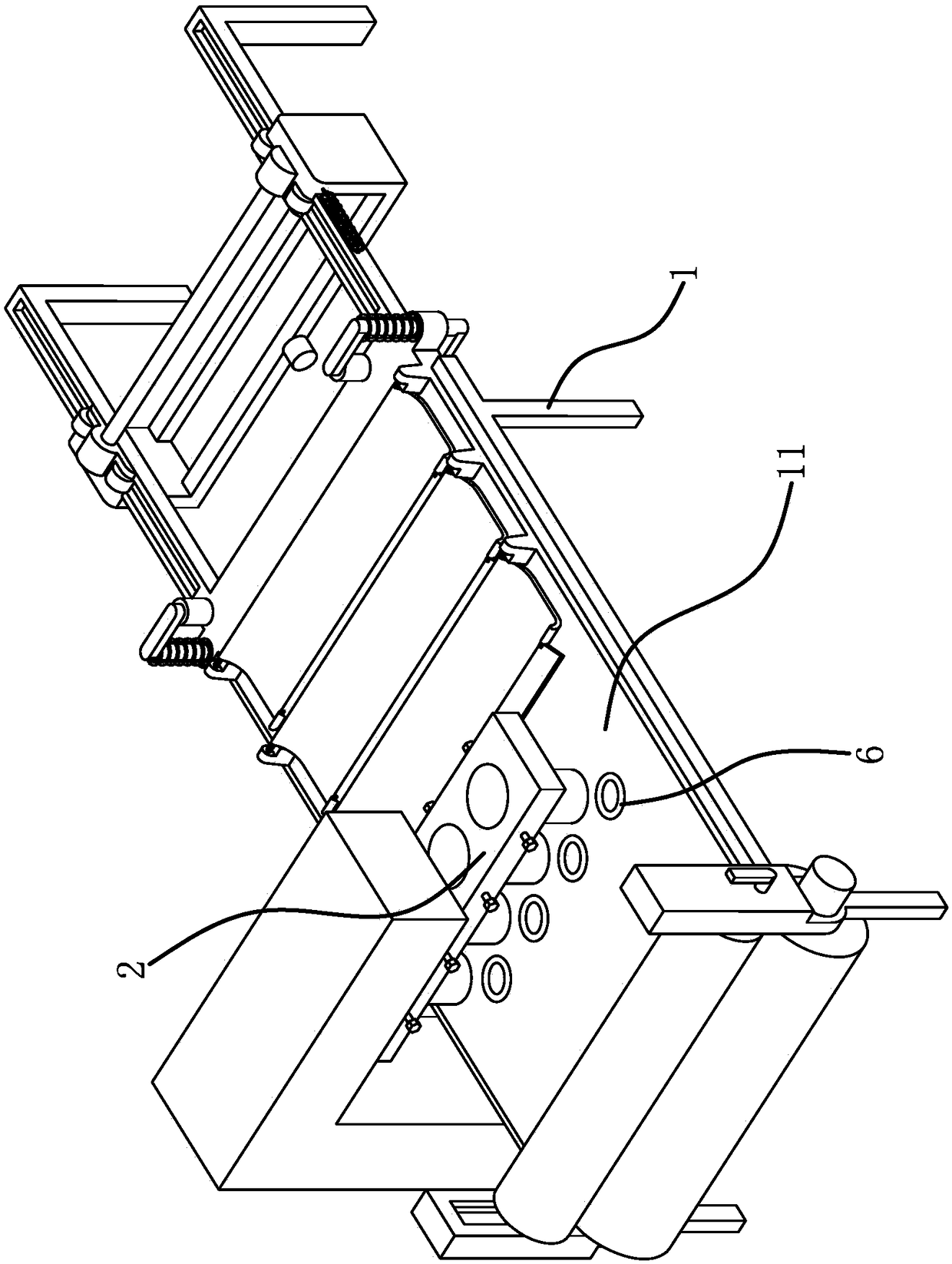
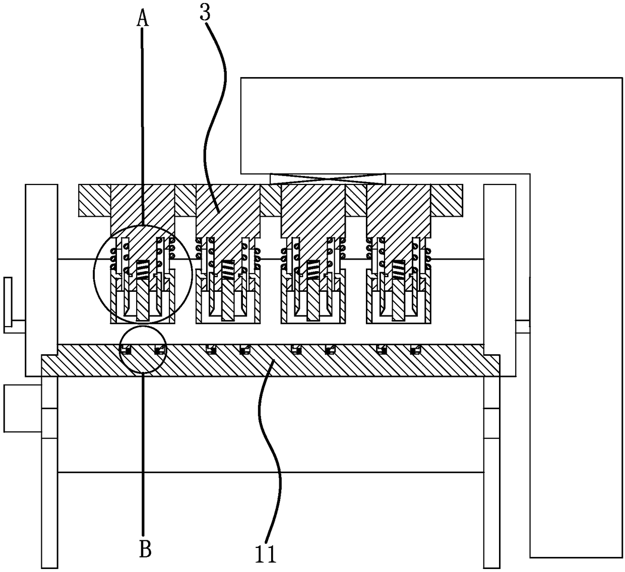
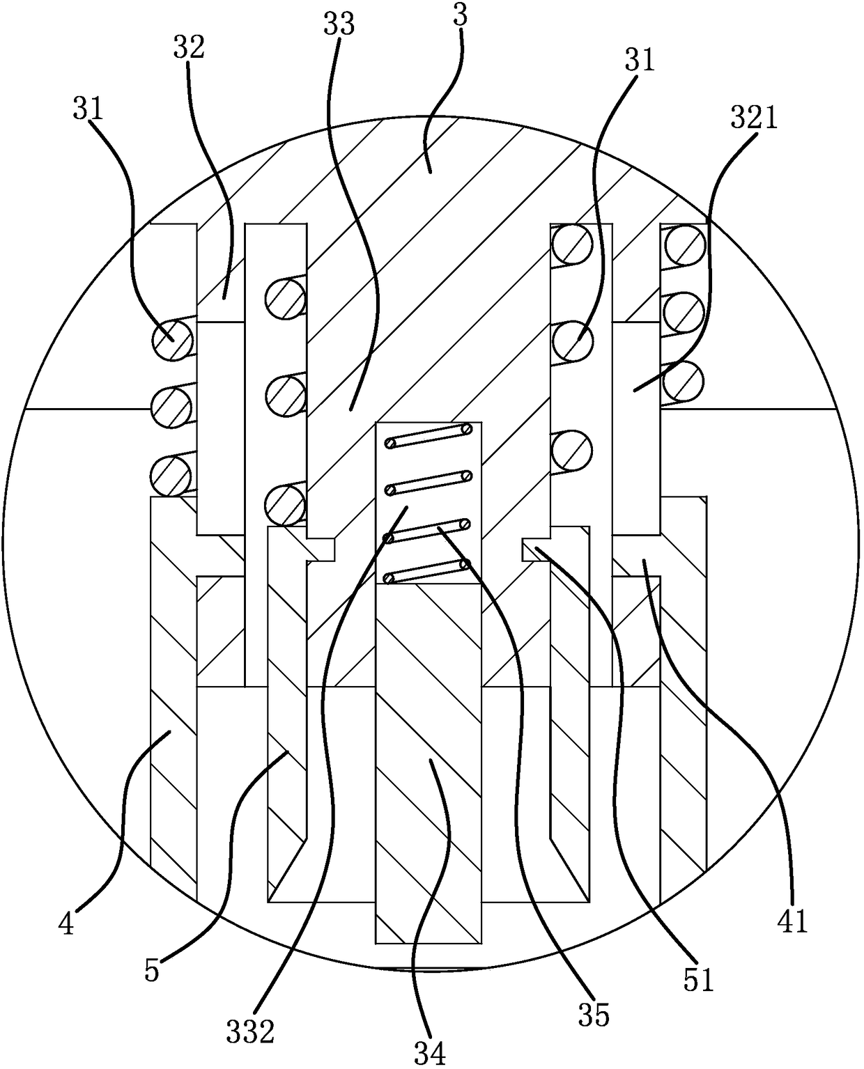
[0021] Such as figure 1 , figure 2 , image 3 As shown, a punching mechanism of a punching machine includes a frame 1 on which a punching platform 11 is fixedly connected. The punching mechanism includes a lifting platform 2 slidably connected to the frame 1 in a vertical direction. The table 2 is located above the stamping platform 11. A number of stamping heads 3 are fixedly connected to the lifting platform 2 along the width direction of the stamping platform 11. The stamping head 3 is slidably sleeved with a positioning cylinder 4 and a cylindrical cutter head 5 in the vertical direction. The cutter head 5 is located inside the positioning cylinder 4, and the lower edge of the cutter head 5 is a cutting edge. The positioning cyl...


PUM


Abstract

The invention provides a punching mechanism of a punching machine and belongs to the technical field of mechanical equipment. The punching mechanism of the punching machine solves the problem that the punching quality of an existing punching machine is low. According to the punching mechanism of the punching machine, the punching machine comprises a rack, and a punching platform is fixedly connected to the rack; the punching mechanism comprises a lifting platform, and a plurality of punching heads are fixedly connected to the lifting platform; each punching head is slidably sleeved with a positioning drum and a tool bit, wherein punching springs enabling the positioning drum and the tool bit to have a downward moving tendency are arranged on the positioning drum; a transmission piece enabling the corresponding tool bit to circumferentially rotate when the corresponding tool bit moves downwards and abuts against felt is installed between each tool bit and the corresponding punching head; and a retainer is installed on the punching platform. The punching mechanism of the punching machine can achieve higher felt punching quality.

Description

Technical field [0001] The invention belongs to the technical field of mechanical equipment and relates to a punching mechanism of a punching machine. Background technique [0002] In the ordinary sense, the punching machine drives the flywheel by a motor, and drives the crank connecting rod mechanism to move the slider up and down through the clutch and transmission gear, and drives the punching die to punch the workpiece. In addition to forming the workpiece, stamping also has the function of punching and cutting, that is, the workpiece can be punched down according to the set stroke, such as punching a circular felt sheet, which is punched by a cylindrical cutter head, but because the felt sheet is a flexible material , There will be displacement and deformation at the moment of stamping, resulting in irregular shapes of stamped felt sheets and lower stamping quality. Summary of the invention [0003] The purpose of the present invention is to solve the above-mentioned problem...

Claims


Application Information

Patent Timeline
Patent Type & Authority Patents(China)
IPC IPC(8): B26F1/40B26D7/01B26D7/18B26D7/08
CPCB26D7/015B26D7/08B26D7/1818B26F1/40
Inventor 王越成
Owner 海宁英和金属制品有限公司
Why Eureka
Try Eureka